• Please review our updated Terms and Rules here

Reviving the PDP-12 at the RICM

But it isn't

First time I have seen that. Another good tip from this forum. Thanks again, Folks!

"The PVA material between the tube face and the blast shield decays with age.."

I'm unfamiliar with this "PVA material". What is it and why was it put in there? Does it get replaced or is it OK to leave out?
 
Last edited:
It's called Cataracts to the TV collectors. The PVA material between the tube face and the blast shield decays with age, leaving the spotty mess you see there.
There's a complete video on how to remove it here, and here's some photos when I did the same to my VR201.
I see it a lot in old terminals and video displays. No make or model is immune to it.

That doesn't look so difficult.
 
Folks,

I'll also throw out for consideration the hot wire technique for removing the safety glass. I have used that with good success. I used a piece of steel wire, about 26 or 28 gauge, wrapped around and held between the two large alligator clips of a 10A car battery charger. The wire heats up and you can saw back and forth through the adhesive. Once the cover glass is off, the whole mess cleans up nicely with acetone and single edge razor blades.

Lou
 
I used a piece of steel wire, about 26 or 28 gauge, wrapped around and held between the two large alligator clips of a 10A car battery charger. The wire heats up and you can saw back and forth through the adhesive. Once the cover glass is off, the whole mess cleans up nicely with acetone and single edge razor blades.Lou

That sounds less dangerous than hearing a piece of glass with a hot air gun.
 
Without the glass you will have a loose fit when the tube is reinstalled, plus you are completely removing a rather critical safeguard should the tube implode.
 
Without the glass you will have a loose fit when the tube is reinstalled, plus you are completely removing a rather critical safeguard should the tube implode.

I put the glass back the same way Next did. I used double sided foam tape to space the cover glass back on the front of the tube. Indeed the fit would be too loose without the cover glass. As for the safety, well, I am sure that the layer of adhesive was intended to be part of the system. I am not too worried however. If you have ever seen a broken face of a picture tube, they are extremely thick to begin with.

Lou
 
Last week we reassembled the PDP-12, reformed the capacitors in the power supply and performed the initial power-on checkout. Nothing caught on fire so we fiddled with the front panel to see if there were any signs of life. The core memory didn't work, and some if the front panel indicators didn't behave as expected. Not unusual for a 43 year old system that has not been powered on for 25 years.

After reading the manual and getting instructions from Warren, we found that some of the misbehaving front panel was due to operator error. The Mode switch to change between LINC and 8 operation doesn't do anything until the I/O Preset switch is pressed. That is working correctly. When you press I/O Preset the INST FIELD is set to 1 and the DATA FIELD is set to 3. I though that this was wrong for an 8k machine. If you look at the front panel picture you will see three bits for the INST FIELD and DATA FIELD then an additional 2 bits. So part of this is for the 8 and all of it is for the LINC and it is working correctly.

We received lots of comments on reforming the capacitors in the power supply and strong recommendations from experts to just replace them. Since new caps are a different physical size, and would cost about $250 we decided to continue with reforming the originals.

The core memory doesn't work so we measured the ripple on the -30V (the main voltage for the core) on the processor backplane. The ripple was about 800mV, a sign that the caps in the power supply were not working well, and probably too noisy for the core to work.

We started the processor checkout and found that bits 4 and 11 in the Program Counter were always on. We looked at the flip-flops in the processor that make up the PC register and they had the correct contents. We need to determine why the indicator lights on the front panel do not exactly reflect the internal state of the registers in the processor so we can continue debugging.

After running the system for about four hours the ripple on the -30V was down to 180mV, so the capacitors are getting better. More run time will hopefully reduce the ripple to an acceptable level. If not, we will have to replace them.
 
Hi All;

I am not a fan of re-forming the Capacitors, but, that is from Old Tube Radio's and TV's, where the Caps are alot Older and the Voltages are alot higher..
On the PC not showing up correctly on the Front Panel, I would check next the connection(s) and make sure that You have a good one and not corroded or wire failure..

Keep up the good work and keep us informed..

THANK YOU Marty
 
After running the system for about four hours the ripple on the -30V was down to 180mV, so the capacitors are getting better. More run time will hopefully reduce the ripple to an acceptable level. If not, we will have to replace them.
Considering how much people want for -12's right now (didn't one sell on ebay last year for $16K or something dumb close to that?), Investing $250 in new capacitors, original size or not, is a very good investment.
 
Considering how much people want for -12's right now (didn't one sell on ebay last year for $16K or something dumb close to that?), Investing $250 in new capacitors, original size or not, is a very good investment.

If the ripple on the power supplies doesn't come down to a reasonable value we will have to replace the caps. Unfortunately modern caps of the same value, but a higher voltage rating, are smaller in diameter. We would need to redrill the terminal holes in a PCB in the power supply, to mount the modern caps. We would also lose the original look of the caps, about the size of two Fosters beer cans end to end. We will know soon enough if we need to replace them.
 
Hi All;

Just a thought, We do it all of the time on Old Radio's and TV's..
Take the inside of the Old Cap out, and put the new one inside, attach it to the Old Terminals and RE-Mount it to the PCB..
That way it looks Original, but it has the Protection of a New Cap (on the inside)..
Look here and there are others for information on doing this..
Bob
https://www.youtube.com/user/bandersentv/videos
https://www.youtube.com/watch?v=__jGjancbP4 and
https://www.youtube.com/watch?v=WOlH5hVajco and
https://www.youtube.com/watch?v=B8IEG3vUDoE
and Dennis
https://www.youtube.com/watch?v=azc2RRQw6Tk

THANK YOU Marty
 
Last edited:
Hi All;

Just a thought, We do it all of the time on Old Radio's and TV's..
Take the inside of the Old Cap out, and put the new one inside, attach it to the Old Terminals and RE-Mount it to the PCB..
That way it looks Original, but it has the Protection of a New Cap (on the inside)..
THANK YOU Marty

That would work.
Probably nasty stuff in the old caps though.
 
Hi All;
M-Thompson, Thank You for looking at the suggestion..
"" Probably nasty stuff in the old caps though. ""
I'LL bet You could handle it and it's not as bad as You might think..
Also, by putting another newer cap on the inside, You can use wire end caps, and so don't need the special type of Cap with the metal ends on them, which makes them more expensive.. And (If possible) I would get double the voltage rating and as near to what its value is, as what is available..

THANK YOU Marty
 
Last edited:
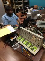
On Friday we removed the front panel for test and repair. That was a bit of a project because of the long flexprint cables that go from the front panel to the processor chassis in the back of the cabinet. We used Warren's flip-chip tester to activate the individual inputs to the M900 flip-chips and found that SN7400 E3 was bad. That was causing the PC05 light to always be on. We found three bad bulbs, and a few that were not making good contact. So, now we think that the front panel is working and we can rely on of for debugging.

This system allows you to enter one instruction in the left switches and the execute it with the DO switch. Even with the core memory not working this let us try a few instructions. In 8-Mode the CLA, ION, IOF, and CAM work. The INA works, but increments from bit 10 instead of bit 11. The Instruction Register has bits 6, 8, and 9 stuck on so that will affect out debugging. We think that some of the SN7474 ICs on the M216 cards that make up the IR. We will test and repair them today.

This is Warren testing the PDP-12 front panel.
Testing_the_PDP-12_Front-Panel.jpg
 
We didn't know if the front panel or the processor was misbehaving, so it wasn't useful for debugging. We replaced a bad SN7400 driver chip and three bad bulbs. Now that we know that the front panel works correctly we can trust what we see for debugging information. Yes, it was cool playing with a front panel that has 120 light bulbs.

On Friday we tried a few of the PDP-8 and LINC instructions. This machine will let you put an instruction in the left switches, and execute it without storing it in memory. Since the memory was not working this was really helpful. We found that some if the PDP-8 instructions worked, many didn't, and none of the LINC instructions worked. We noticed that some of the bits in the Instruction Register were stuck on, so we suspected the instructions that we tried were not being interpreted correctly.

On Saturday We swapped the two M216 (six flip-flops in three SN7474 ICs) flip-chips that make up the IR and the stuck bits moved. We replaced the broken M216 with a spare, and now all of the IR bits worked correctly. With a working IR, we found that lots of the PDP-8 instructions, and many of the LINC instructions now worked. We could turn the relays on and off and make noises through the speaker.

We have replaced LOTs of SN7474 ICs on other DEC machines, so we pulled all of the M216 flip-chips and ran them in Warren's tester. We found and replaced another bad M216, the one that controls the core memory states. Now core memory works!

We went through the troubleshooting guide in Maintenance Volume-II. It gave a procedure for doing a quick test of core memory. It revealed a problem in the upper addresses. From the prints it had to be one of two G221 flip-chips. We swapped in a spare and found that the one in slot C09 was bad. Now all of the bottom 4k of memory works.

There is a problem with any PDP-8 instruction that has an address in the lower 9 bits. All 12 bits of the instruction are used, so it makes a mess. Debugging that issue will be the next project.
 
Since SN7474 and SN7400 ICs seem to be a problem in these early DEC systems, we pulled all of the M113 flip-chips and tested them. The ones in slots J33 and K30 were bad. Replacing them fixed the problem with the JMP instruction.

We did some more testing with the toggle-in programs and found that ISZ cleared the AC. Replacing the M119 in slot H28 fixed that.

Core memory in field 1 with addresses X5XX didn't work. We replaced the G221 in slot D10 to fix that.

We tried the ASR33 Teletype that came with the system. The mechanics were sticky from not being used for 30 years, but we got most of it free and working. We could send characters to the Teletype, but could not receive anything. The M706 receiver failed in the board tester. The spare is also broken, so we need to fix both.

All of the toggle-in tests pass, so the processor is now substantially functional.
 
Back
Top