• Please review our updated Terms and Rules here

RK05 disk emulator development and discussion

I received my package today.
George does an amazing job of packing. Look at the attached picture.

Kudos George.

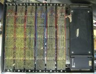
Now it's time to put it together.

And pre-assembled surface mount boards, Impressive.
Thanks Mike! There are so many small parts. It seemed necessary to have them organized. The assembly instructions refer to parts in specific bags so it’s easier to find things. Inspired by building Heathkits a “few” years ago.
 
Thanks Mike! There are so many small parts. It seemed necessary to have them organized. The assembly instructions refer to parts in specific bags so it’s easier to find things. Inspired by building Heathkits a “few” years ago.
Prusa does that with their 3D printer kits too.
 
I agree - George's kit is one of the nicest I have ever received. Everything is nicely labelled and the instructions are easy to follow. I have seen others were everything was just in one large bag.
 
Excellent job!
Thanks! Much appreciated!
Will there be a firmware update for the PDP-11/RK-11 environment ? Or is it already supported?
I believe PDP-11 12-sector mode is already supported.
However, it's only been tested in 12-sector mode using the emulator as a tester connected to another emulator operating in 12-sector mode. It's possible I could have interpreted the behavior incorrectly on both sides but both talk to each other just fine.
A header in the data file on the microSD defines the drive parameters.
I'd really like to have someone test the emulator with an RK11-D or E or C
 
This whole project looks really great! I love the 3 drive rack mount look. I just wish I had something that could hook up to it. All I have in PDP-8 land is a PiDP-8 and a Spare Time Gizmos SBC6120. My PDP-11's are of the micro variety So I'd need the QBus version of the RK11 (RKV11-D) box/backplane. There happens to be one on Ebay but the price is a bit out of my range. :)
 
I have a bunch of machines with RK11-D but they are not tested and thus I don't know if there might be a fault in the controller or if your drive-emulator has a bug. If no one else step forward and want to test the emulator on a RK11 I can do it but others with known working RK11 should take precedence. Let's wait a week or so and see what happens.
 
I have a bunch of machines with RK11-D but they are not tested and thus I don't know if there might be a fault in the controller or if your drive-emulator has a bug. If no one else step forward and want to test the emulator on a RK11 I can do it but others with known working RK11 should take precedence. Let's wait a week or so and see what happens.
What type of Unibus backplane does one need for the RK11-D? Is it feasible to custom wire-wrap a suitable backplane?

I didn't have a functional RK05, but before I started the emulator testing & debugging with the RK8E I was able to confirm that the controller was essentially functional using the PDP-8/e "Diskless Control Test" - "maindec-08-dhrka-e-pb" downloaded from Vince's site. You might find something similar for the PDP-11.
 
What type of Unibus backplane does one need for the RK11-D? Is it feasible to custom wire-wrap a suitable backplane?
It's a 4-slot variant of a DD11-A or DD11-C, although any backplane that is based only on wire-wrap could be used after you strip it down. If the backplane is all or in part based on a PCB then I think that you're stuck with committed connections that can't be uncommitted. The RK11-D FMPS includes diagrams of the slot-signals as well as the wirelist.
 
It's a 4-slot variant of a DD11-A or DD11-C, although any backplane that is based only on wire-wrap could be used after you strip it down. If the backplane is all or in part based on a PCB then I think that you're stuck with committed connections that can't be uncommitted. The RK11-D FMPS includes diagrams of the slot-signals as well as the wirelist.
Thanks Paul, as it turns out I have a DD11-C, so it might just work out of the box. You said variant - how do I check that I have the matching/correct variant for the RK11-D board set - your answer seems to imply that not all RK11-D backplanes are identical?
Sorry for the dumb question, but there are still a lot of mysteries for me in the PDP-11 world - what is a FMPS?

Tom
 
Thanks Paul, as it turns out I have a DD11-C, so it might just work out of the box. You said variant - how do I check that I have the matching/correct variant for the RK11-D board set - your answer seems to imply that not all RK11-D backplanes are identical?
The DD11-A and -C are 4-slot backplanes wired for Small Peripheral Controllers (SPC), one per slot. By "variant" I meant that input/output slot-tabs (tabs A-B in the first and last slot) will be Unibus standard, but the remaining tabs in the first and last slots and all of the tabs in the other slots will likely be wired differently depending on the nature of the controller module-set.
Sorry for the dumb question, but there are still a lot of mysteries for me in the PDP-11 world - what is a FMPS?
Field Maintenance Print Set; I had to learn that one too! Sometimes also referenced as "Engineering Drawings". Examples:

 
Hmmm - I am not much wiser after reading through the documents above.
I still don't know if the backplane I have is suitable for the RK11. I suspect the answer is no.

Here are photos of what I have:

PXL_20240515_130259141.jpg

PXL_20240515_130314314.jpg

PXL_20240515_130343346.jpg

So is this a backplane for a RK11-D - a Unibus based RK05 controller consisting of the boards M7254, M7255, M7256 and M7257?

Thanks
Tom
 
So is this a backplane for a RK11-D - a Unibus based RK05 controller consisting of the boards M7254, M7255, M7256 and M7257?

Thanks
Tom
No. It's suitable for hosting up to 4 SPC modules. It does appear that if you strip off all of those WW wires, and ignore the traces feeding the 2x5 connector, that you possibly could successfully repurpose it. Although you'd want to carefully scrutinize the PCB for other traces (which would include the non-visible surface) before proceeding. A PCB-free backplane (like one of the three rightward ones in the attached photo) would be a risk-free starting point, but that's not what you have there.
 

Attachments

  • 11_15 Backplanes.jpg
    11_15 Backplanes.jpg
    257.4 KB · Views: 13
No. It's suitable for hosting up to 4 SPC modules. It does appear that if you strip off all of those WW wires, and ignore the traces feeding the 2x5 connector, that you possibly could successfully repurpose it. Although you'd want to carefully scrutinize the PCB for other traces (which would include the non-visible surface) before proceeding. A PCB-free backplane (like one of the three rightward ones in the attached photo) would be a risk-free starting point, but that's not what you have there.
Thanks Paul.
It is a bit disappointing. For a moment I thought I have all the pieces of the puzzle to get George's nice RK05 emulator working on my PDP-11/34. Omnibus is much easier.
I still have a RL11 controller to get through my repair pipeline before I can use the RL01/RL02 emulator.
 
Roland,

Speaking of kits, is your new memory/boot/etc. board done? If yes, can I get a kit, if not I would like to request a slight modification to it.

Also, I have added Vince's Console Serial Port Disk boot loader to the bootloader code. I have hooked up a 2 x 20 line I2C display with push buttons on it to display information like what is being booted and possibly more. So the modification would be to bring out the I2C pins to a connector or just to pads/plated thru holes on the PCB.

I am also thinking of doing a version with a small graphic display with a touch screen. Also I2C.

Thanks,

Mike
 
I don't have a spare RK11-D backplane but as I am also in Oz I could conceivably lend you one if you can't snag one from somewhere.
With it, maybe you could buzz out the pins (yes I know there is a wirelist) into an Excel table or something, then use a Dremel and diamond cutoff wheel to slice your DD11's PCB into isolated sections. Or maybe make a tubular drill from a large-bore hypodermic needle with the end sharpened then slipped over the wire-wrap pin and finally drilled carefully in a drill press. I think this could be enough to isolate it perhaps.
Then re-wire wrap the whole gubbins using the wirelist backed by physical verification with the real backplane. Does this sound workable?

I was already contemplating something similar to the above regarding a DD11 rewire not long ago with the future (pipe) dream of a recreated KE11-A, as my FOX-2 11/15 once had one in it. But now that the Unibone can do this it's probably not worth bothering about anymore.
 
I don't know how these are held together, but wouldn't it be simpler to just mount 3 connector blocks onto a strip with the required spacing, then wire-wrap from there? I seem to recall I have some old backplanes that are just a square "rod" with tapped screw holes in the right places, and then you screw down the connector blocks. (The rod typically also has plates mounted to the ends, which carry the part number and barrier strips for the margin check circuitry.)
 
I don't know how these are held together, but wouldn't it be simpler to just mount 3 connector blocks onto a strip with the required spacing, then wire-wrap from there? I seem to recall I have some old backplanes that are just a square "rod" with tapped screw holes in the right places, and then you screw down the connector blocks. (The rod typically also has plates mounted to the ends, which carry the part number and barrier strips for the margin check circuitry.)
Well,, yes and no. The PDP-8 orientation of the blocks along the mounting rod isn't the same as the PDP-11 orientation in a system unit. Electrically, no problem. Mechanically there will be fair amount of work to construct a mounting frame to hold the blocks together in the correct alignment. But I expect that it can be done :-}!
 
Back
Top