• Please review our updated Terms and Rules here

RK05 disk emulator

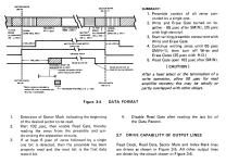
here are the timing specs for the diablo sync fields in a sector
header and data and bit order in the sector data are dependent on the format implemented by the controller
the information manual on the model 30 mentions 8-24 sectors are supported
quickly looking, i've seen 8,12,16 and 24 sectors used by various systems. 12 is used on pdp-11s, 16 on pdp-8s
 

Attachments

  • diablosync.png
    diablosync.png
    139.5 KB · Views: 10
Short update info: The RK05-emulator prototype interface board is now complete. The attached
picture shows the proportions to the DE10-Nano board (I'll never do anything like that again
in my old age). Detailed information can be found on my homepage or on GitHub in the
RK05-Emulator.pdf file. The output signals are driven by a 74ls07 open collector chip.
Developing a PCB board will take time but is starting and making by a friend.
Two minor problems are still open:
1) I don't quite understand the "BUS RK11D-L @U1" signal. Do I have to implement it ?
2) The signal @ A08-M2 is hard to read everywhere in the drawings and appears 2 times.
I assume that the signal R/W/S READY L is on A08-H2.
A few words about your inputs: I have no experience with the Diablo 31 disk drives,
but I think that the emulator can be adapted relatively easily for these disks as well.
However, the main problem will be the hardware, i.e. the connectors and the design
of a PCB board. The design of my RK05 emulator is able to support up to 4 drives
simultaneously in a mixed environment of emulated and real RK05 drives. I have
implemented it in such a way that drive no. 0 to 3 are configured selectively via
the switches on the DE10-Nano board.
The topic "number of sectors" would not be a problem for the FPGA. Only changes in
a verilog program would be necessary (Your reference to the Pertec D3000-series).
Lastly, I never found out about Carl's work. Shame, an exchange of views would
probably have been helpful.
 

Attachments

  • Board_3.jpg
    Board_3.jpg
    1.4 MB · Views: 41
Short update info: The RK05-emulator prototype interface board is now complete.
Excellent!
Detailed information can be found on my homepage or on GitHub in the RK05-Emulator.pdf file.
Thanks for posting. I’m eager to take a look.
1) I don't quite understand the "BUS RK11D-L @U1" signal. Do I have to implement it ?
It depends on the functionality that you’d like the emulator to have. The BUS_RK11D-L signal controls whether the four bus select signals act as individual select lines as output by the RK8-E, or as three binary encoded select signals (with the 4th signal unused) as output by the RK11-D.

There’s a snippet of the circuit in the RK05 that implements this signal selection in this post:
 
FYI
Thanks for these references. Although, I ended up spending much more time than I imagined reading a bunch of interesting unrelated stuff in Carl's blog archive and kept following links forward to more recent work.

The device that Carl built is emulating the controller side, and it appears he used this to read and copy disks from real drives. It would be the perfect test device for the RK05 emulators that Reinhard and I are working on. Reinhard has also described a controller-side emulation using similar (but flipped) hardware as the RK05 emulation.

I was planning to build a partial emulation of the controller function in a larger ice40HX FPGA proto board that I already have. The purpose of this is to debug and verify the RK05 emulator, but not a fully-functional thing to read/copy entire disks. The tester will probably use push-pull drivers, no terminations, no M930, and a short cable from the tester to the RK05 emulator.

Getting Carl's work would be useful to you.
He promised to build one for me, and ended up just returning the FPGA board
AFAIK, none of his work was ever documented.
That's unfortunate. He's described much work so well in the blog. I'm envious. Looks like a lot of fun.
The big issue he ran into was getting enough drive strength on the control bus drivers.
I can imagine how this could be. Drivers need to sink about 56 mA (and a little more with resistor and supply tolerances) due to the M930 termination plus terminations on the controller side. I'm planning to use the same SN75451/SN75452 drivers (SO-8 package though) that are used in the RK05, RK8-E and RK11-D/E.
 
Could someone clearly write down what the bit timing and layout of RK05 sectors are for 16 and 12 sector packs?
I looked at what is documented in the new work so far and it is pretty opaque. It isn't even very clear how read and write gate are being used
which are necessary to get the data splices correct.
 
Hopefully soon I'll have access to a real and working RK05 to measure the sector timing
with a logic analyzer and clear up any ambiguities. gwiley has already described the
most important information, especially in the PDP8 environment, here.
Does anyone know what's going on with Roland (https://github.com/Roland-Huisman) ?
I can not reach him. Think he has all the RK05 @ PDP-11 related information needed.
 
Could someone clearly write down what the bit timing and layout of RK05 sectors are for 16 and 12 sector packs?
I looked at what is documented in the new work so far and it is pretty opaque. It isn't even very clear how read and write gate are being used
which are necessary to get the data splices correct.
I think I have most of this gleaned from the maintenance manual and schematics of the RK8-E and RK05, and also from the training manuals for the RK05.
I put this into a document that has been a nice reference for developing the FPGA code.

It would be helpful to organize it a little better before sharing.
 
Oh, one more thing. Is the 18-bit mode (RK11-E) used much? This mode has 12 sectors per track, 18 bits per word.
The reason for asking is the bit rate is 1.545 Mbps rather than 1.44 Mbps which is used with the RK8-E and 16-bit mode RK11-D.

For now, I've assigned a mode bit for this but it's not connected to anything. Might support it later if this mode is useful. (Probably would use the FPGA on-chip PLL to synthesize either 1.44 or 1.545, but I haven't seriously investigated the implementation.)

1680468544301.png
 
Last edited:
Have been making some progress on the emulator. Schematic and PCB layout is about complete.
v0x2 PCB image front side.jpg v0x2 CCA Virtual image front side.jpg

FPGA modules are coded and unit-test simulated.
While JLCPCB is doing PCB fab and board assembly, the next phase is to work on software, front panel, mechanical design and test jigs.

The plan is for this to look very much like an RK05 but a lot smaller, same switches and lights. Should be able to fit three across on a 19" rack shelf and would be 2U high.
Each emulator can be powered by a USB adapter. Not exactly certain yet what the exact +5V current consumption will be, but quite small compared to the M930 termination board (which is ~0.5 to 1.0 A depending on the state of the bus, idle or max number of signals active.)
 

Attachments

  • RK05 disk emulator FPGA modules.pdf
    422.1 KB · Views: 12
  • RK05 Emulator Schematic v0x2.pdf
    1.5 MB · Views: 9
  • SDRAM Controller State Machine v00.pdf
    431.4 KB · Views: 9
A step closer to having real hardware. Received the assembled boards back from JLCPCB and have soldered most of the miscellaneous through-hole stuff. Haven't powered it up yet and haven't yet installed the FPGA. I forgot to order the serial configuration memories so that's gotta happen ASAP. Plan to power up first to test voltages, the clock oscillator and the Raspberry Pi Pico while plugged into this board.

Fortunately, I have an M930C terminator board so that'll make it a bit easier to verify that some of the I/O signals can toggle.

There's a separate front panel board and separate microSD adapter board that aren't built yet.

RK05 emulator photo first build no FPGA.jpg
 
Last edited:
wouldn't it have made more sense to have the provision for daisy chaining with something other than unibus cable?
I suppose for the 3 on a panel case you could make paddle cards to bridge them
 
provision for daisy chaining with something other than unibus cable?
Yes, spare/extra Unibus cables aren't all that common nowdays.
I'd think that the typical 40-pin (80-wire) IDE/UDMA cable would likely work well enough for short-length daisy chaining. Perhaps a larger Rev. 2 board design could include 40-pin headers next to the DEC-style connectors to allow using either type of cable? Or like Al suggests, adapter paddle cards could be designed to convert 'Unibus' to 40-pin IDE cable (for short lengths).

If someone wanted to make replacement Unibus cables, what would work? The original 60-conductor Flexprint cable doesn't seem readily available.
 
wouldn't it have made more sense to have the provision for daisy chaining with something other than unibus cable?
I suppose for the 3 on a panel case you could make paddle cards to bridge them
I agree, and that was my original plan to put a pair of 40-pin headers next to each edge connector. However, it was quite difficult to fit them in with the size of the headers and sufficient clearance to plug in the cable. Could've made the board larger... the unit would be 3U instead of 2U.
Plan B is to build little double-height paddle cards with two 40-pin latching headers. The pinout will correspond to the RK8E so the flat cables from the paddle cards can plug directly into the controller.

Could've used header connectors instead of edge connectors, but I wanted this to be as much like a real RK05 as possible so the emulator can be connected exactly like a real drive.
 
Yes, spare/extra Unibus cables aren't all that common nowdays.
I've noticed that too. I think I've only seen them once on ebay.
I'd think that the typical 40-pin (80-wire) IDE/UDMA cable would likely work well enough for short-length daisy chaining. Perhaps a larger Rev. 2 board design could include 40-pin headers next to the DEC-style connectors to allow using either type of cable?
That could work. There's also spectra-strip cable that has twisted pairs and is flat every 20-inches or so to allow placement of an IDC connector. Those are easy to make in my garage with a vice to clamp the IDC connector.
Or like Al suggests, adapter paddle cards could be designed to convert 'Unibus' to 40-pin IDE cable (for short lengths).
That's the plan right now. I need a way to connect the first drive to the controller so the one paddle card design can serve both purposes (controller to first drive and drive-to-drive).
If someone wanted to make replacement Unibus cables, what would work? The original 60-conductor Flexprint cable doesn't seem readily available.
The cable I'm thinking about will connect drive-to-controller and drive-to-drive. Not certain whether it'll work for Unibus but will be compatible with the RK8E and RK05. RK8E has all signals paired with ground on the adjacent pin.
 
Last edited:
I'd think that the typical 40-pin (80-wire) IDE/UDMA cable would likely work well enough for short-length daisy chaining. Perhaps a larger Rev. 2 board design could include 40-pin headers next to the DEC-style connectors to allow using either type of cable? Or like Al suggests, adapter paddle cards could be designed to convert 'Unibus' to 40-pin IDE cable (for short lengths).
I recently had some of these M9042 clone paddleboards by Jay Logue fabbed, now I'm just waiting on the 40-pin right-angle IDC ejector headers to arrive:
https://github.com/jaylogue/m9042-clone

The minimum order was 5, so not sure what the 5th one would be good for.
 
Yes, spare/extra Unibus cables aren't all that common nowdays.
I'd think that the typical 40-pin (80-wire) IDE/UDMA cable would likely work well enough for short-length daisy chaining. Perhaps a larger Rev. 2 board design could include 40-pin headers next to the DEC-style connectors to allow using either type of cable? Or like Al suggests, adapter paddle cards could be designed to convert 'Unibus' to 40-pin IDE cable (for short lengths).

If someone wanted to make replacement Unibus cables, what would work? The original 60-conductor Flexprint cable doesn't seem readily available.
Are these flexprint UNIBUS extension cables (BC11A) really that hard to find these days? I've got a decent quantity of them in my collection (I'd say at least 20) - honestly, I didn't really value them that much as the friend that got me into PDP11's kept telling me "oh there's lots of those on eBay and third party versions are easy to find". Funny enough, I just did a quick eBay search and came-up with nothing.

I'd be more than happy to donate a couple to help with the project if someone needs some. I prefer M9042/M9014's myself as I find the BC11A cables hard to work with and are quite delicate, whereas typical your typical ribbon cable is quite rugged in comparison.

-Chris
 
I recently had some of these M9042 clone paddleboards by Jay Logue fabbed,
Always happy to see someone making use of my little project! (y)

Are these flexprint UNIBUS extension cables (BC11A) really that hard to find these days?
In my experience these cables are relatively rare. Took me quite a while to acquire the one I have, and unfortunately its not in great shape (foam lining is disintegrating).

Of course with my M9042 clone I didn't really need it. However since I have an actual use for a Unibus interconnect (11/05 to ME11), I thought it would be nice to have authentic DEC hardware.
 
Always happy to see someone making use of my little project! (y)


In my experience these cables are relatively rare. Took me quite a while to acquire the one I have, and unfortunately its not in great shape (foam lining is disintegrating).

Of course with my M9042 clone I didn't really need it. However since I have an actual use for a Unibus interconnect (11/05 to ME11), I thought it would be nice to have authentic DEC hardware.
Yeah, the foam is disintegrating on all of the DEC BC11A's now... I even have one new-old-stock, peeked at it and yup the foam is breaking down. I've got at least one 3rd party cable where they used a different brand/type of foam and it's still good.

-Chris
 
Yeah, the foam is disintegrating on all of the DEC BC11A's now... I even have one new-old-stock, peeked at it and yup the foam is breaking down. I've got at least one 3rd party cable where they used a different brand/type of foam and it's still good.

-Chris

I still can remember the "fun" i had when i had to clean those cables, the longest about 3 meters if i remember correctly.
But figured some defective out while doing this...
 
Back
Top