• Please review our updated Terms and Rules here

RK11-C / RK05 restore

fritzm

Experienced Member
Joined
Dec 11, 2011
Messages
142
Location
Oakland, CA
Hi folks!

Kicking off a thread here because I'm just starting to dive in on the storage subsystem of my PDP-11/45: and RK11-C + 2x RK05, and I'll be wanting to take advantage of the collected wisdom and good advice here. There's been a fair amount of talk on RK05s here and on the cctalk, and I've read up on all of that and am pretty encouraged. So far, I've gone through cleanup/refurb of the H720e supply for the RK11-C, and have dusted, cleaned, and re-racked the controller.

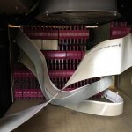
First problem: there are a handful of resistors and caps mounted directly on the backplane via crimp connectors that slide over the wire-wrap posts. A few of these connectors have broken off and will need to be replaced. I've had some trouble this morning trying to source replacement connectors, but I'm sure its just because I don't know correct names under which to search? What I'm after is a single crimp connector that will connect snugly over a .025 square wire wrap post. The originals look like that are gold-plated brass or tin. Picture below showing some of the undamaged and damaged connectors. Any pointers appreciated!

cheers,
--FritzM.

[Edit: from cctalk: Wouldn't those be plain old 0.025" square socket pins on a strip? http://www.ebay.com/itm/Gold-plated...hash=item33b3bf9e55:m:mkh7h_knuzj5K39hpUzgHaQ]
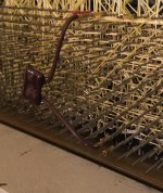
IMG_2483.jpg
 
Last edited:
A short term substitute can be found in the jumper shuts used configuration. Some will slide down over a the wire wrap and the other side can be used for the component.

A better substitute might be something like Molex - 43030-0038 but its not meant to slide all the way down like the original. Check out
http://www.mouser.com/Molex/Connectors/Headers-Wire-Housings/_/N-ay0lo?P=1z0zlewZ1z0spqj


A short term substitute can be found in the jumper shuts used configuration. Some will slide down over a the wire wrap and the other side can be used for the component.

A better substitute might be something like Molex - 43030-0038 but its not meant to slide all the way down like the original. Check out http://www.mouser.com/Molex/Connectors/Headers-Wire-Housings/_/N-ay0lo?P=1z0zlewZ1z0spqj

Thanks! I'll try the jumper idea while I'm waiting for permanent parts in the mail.
 
Update after the weekend: racked, cabled, and powered up the RK11-C. Tracked down and repaired a failed gate in the RKDB register. Now getting a bus timeout in test 21 (controller reset) of the ZRKJE0.BIC diagnostic, which will be the next thing to investigate. More detailed writeup on my blog here: http://fritzm.github.io/rk11.html

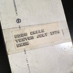
The H720E power supply that goes with my RK11-C is missing its top plate, so it was pretty dusty. I was wondering if anybody recalls if these were left off intentionally for cooling, or if I should fab some kind of replacement?

cheers,
--FritzM.

rk11-back.jpgbc11-good.jpg
 
Do you have a Unibus Terminator far side of the RK11-C? M930?
I can't tell from the picture. Don't recall ever running the power supply for ours open. Too much change of dropping something into the innerds.


See Unibus Troubleshooting User's Manual EK-FS002-OP-00 page B-3 for an example.
 
Last edited:
Do you have a Unibus Terminator far side of the RK11-C? M930?
Yup, sure do. The interesting thing is, for the diagnostic to get this far (which it consistently does) many previous reads and writes to various registers on the controller are succeeding. It seems to be a read immediately following a controller reset that times out.

SSYN comes straight off an M105 address decoder; its a very simple cap-mediated delay and doesn't have any reset/init-related logic that I can see. The only thing I can think of so far is that resetting the controller maybe draws enough current to slightly droop the supply and throw off the timing? I dunno -- I'll scope the rails and throw a logic analyzer on a few of the bus signals next time I have some time to work on it and see if there's anything marginal or fishy looking with the sequencing or timing.

Don't recall ever running the power supply for ours open. Too much change of dropping something into the innerds.
A very good point! I guess I'll cover it. It does have a fan, after all.
 
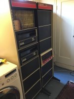
Got a picture of the entire system? Figure an 11/45 with two RK-05 drives you got to have about a thousand pounds of hardware there. Wanted to see if it was just in one or two racks. I have a dual RL drive with an 11/34 but that’s just lightweight to the super heavy RK family of drives. Had one RK-05 that I sold off some time ago and think by the time I got it packed up and ready for shipping it was around one hundred fifty pounds or so without the disk pack.
 
Got a picture of the entire system? Figure an 11/45 with two RK-05 drives you got to have about a thousand pounds of hardware there
Yup, it's a beast (see pic below). I'd been carrying it around in pieces, collecting parts and spares, etc. for years -- finally got to working on the assembly and restoration over the last couple years since my kid is up and out. The whole project is blogged, with many more photos, over at http://fritzm.github.io/category/pdp-11. Getting close now -- have to work through this storage system, then an LA30.

cheers,
--FritzM.

rk11-racked.jpg
 
Some progress on the diagnostic bus timeout issue:

I wrote a small diagnostic that repeats just the part of the DEC diagnostic that was failing. If run in a loop, it would also trap to location 4 after some large number of iterations. Hooked up my logic analyzer to MSYN/SSYN on the RK11-C backplane and set up a trigger to see if I could catch a missing/late SSYN that might be causing a timeout, but didn't see any... Verified that the trigger was working by accessing a non-existent memory location from the front panel.

So the next step was to move back over to the CPU, throw the the UBC card out on extenders, and attach some probes to see why the CPU was taking a trap 4. To my surprise, after doing this, my small diagnostic passed, so checked again and indeed the ZRKJE0.BIC maindec static test is now passing!

So seems it was either a badly seated UBC board, or perhaps more likely the 15-foot BC11 cable that connects the CPU to the RK11-C is flaky or position sensitive? I guess I'll button it up again and see if it keeps working...

The BC11 I'm using looks visually in pretty good shape. It doesn't have the foam separator between the cables, though. Perhaps I should try to track down some appropriate foam and add it.
 
Well, it definitely has to do with having UBC on the extender or not -- this seems to be what's making the difference. Unfortunately, it *works* on the extender, where it's easy to debug... I guess I'll try hanging logic analyzer probes off the backplane pins and see if I can see anything strange...
 
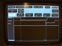
Attached logic analyzer probes to BUS A MSYN L, BUSA SSYN L, and UBCB TIMEOUT (1) H at the rear of the UBC board on the 11/45 backplane, with the UBC board fully seated. Set the trigger on the timeout line, and running my test program I can see that timeout glitches for about 12ns right before the processor takes a trap 4. In every case where this happens, the timing is consistent between MSYN and SSYN -- about 558-558 ns, well under the bus time out. See logic trace below.

I guess I'll need to read up on the 74123 one-shot. Are they known to have glitch issues? If not, maybe I have a failed/failing part and could try replacing it.

Since the timing is consistently +/- a ns or two on every failure, perhaps things work on the extender because it adds a ns or two? I'll try to confirm this theory by inserting a longer BC11 in place of one of my backplane jumpers and see if it changes the behavior.

I think the SSYN signal levels would also be worth a look, but I don't have a digital scope that could capture that -- might be time to get one...

IMG_2506.JPG
 
Confirmed: replaced an M920 backplane jumper with a BC11A-02, adding a couple nanoseconds between the controller and the CPU, and the problem no longer occurs. It looks like the 74123 one-shot glitches only on a very particular stimulus.
 
Confirmed: replaced an M920 backplane jumper with a BC11A-02, adding a couple nanoseconds between the controller and the CPU, and the problem no longer occurs. It looks like the 74123 one-shot glitches only on a very particular stimulus.

Actually DEC deprecated/obsoleted the M920 UNIBUS backplane jumper a long time ago due to its effect on UNIBUS signal integrity. The replacement is the M9202 jumper which has a 24" unibus cable embedded in it to separate the lumped loads on one backplane vs the next one. So the 'time delay' per se is not the problem, but the fact the UNIBUS loads are electrically 'too close' to each other is, causing excessive lumped capacitance vs more distributed capacitance. The M920 has maybe 2" or so of UNIBUS cable in it.

The 1979 version of the UNIBUS Specification (chapter 5) goes into great detail about this issue.

M9202 image: s-l1600.jpg

M920 image: $_57.JPG
 
Last edited:
Ah! Thanks for the info, Don -- I will go read up.

I've got the 11/45 backplane, then a 9-slot DD11-DF, then a 15-ft BC11 cable to an RK11-C. Terminated on one end at slot 01 of the 11/45 with and M9301, and at the other end on the RK11-C with an M930. I'll try to track down an M9202.

To test my understanding: the theory on the timeout glitch then would be excessive lumped capacitance affecting, for example, slew on SSYN? Something I might see on a scope?

thanks,
--FritzM.

With the M920 the lumped capacitance load will be greater at the location adjacent to the M920, so you may see slower edge rates and/or over/undershoot and ringing. If the ringing is great enough the local receivers may see false edge triggers.
 
I found a reasonably priced M9202 on eBay, and also a used digital storage scope that I can start to use along with my logic analyzer. Thanks again for the tip!
 
Okay, I've started to go through one of the RK05 drives, cleaning up all the decaying foam. Filter elbow is intact and still slightly pliable. It's yellowish-white in color, sharpied 8-24-79. It is "shedding" a white powder, so I'll at least need to remove it and clean it -- any advice here would be very much appreciated! This part seems like it would a very good candidate for a modern 3d print replacement -- the tolerances are loose and it doesn't have to carry a lot of stress.

Another question -- what holds the HEPA filter in place on the far end, opposite the elbow? Mine had a velcro strap which I undid, but it still seems to be caught up on something on the far end. I'm hesitant to pull or prod too hard since there is a lot of old brittle plastic about.

Heads look clean and undamaged, and are not coated with oxide.

Pulled the power supply to go over it on the bench; will reform the big electrolytics. Emergency head retract batteries are not yet leaking, so no mess to clean up there, but I'm planning to swap them out proactively.
 
Last edited:
Be careful with the elbow. Some get dried out and crumble.

You have a later revision of drive if you have the elbow. I believe that the HEPA filter just snaps into the plastic on the Velcro end.

Carefully clean the heads anyway. Take a look at them again after you spin up the drive for a few minutes.

I would disconnect the batteries until you replace them. I bought replacement batteries from Batteries America. The are not needed unless the AC power is turned off while the disk is spinning.
 
Okay, took a lot of time thoroughly de-foaming the first of the two RK05 drives. Pulled blower, cards and backplane, ducting, and front panel in order to get at everything and clean up all the mess. Installed some fresh weather-stripping for the cartridge and blower seals.

Power supply tested okay on the bench after a cautionary reform of the big electrolytics. -15V supply was trimmed very hot (-23 or so) so I backed it down a bit. Put everything back together again, disconnected J1 per power-supply checkout in the maintenance manual, plugged in, and... no +15. Pulled the regulator again to check it, and the protection fuse had blown :( Also, when connected to the servo amp board, the -15 regulator was pulled up to about -8V, so that's probably why it had been trimmed hot. Backed it back up to -15V with the servo amp board connected.

So, a couple of questions for folks out there who have worked with these drives:

- Is it normal for the servo amp board to load the -15V supply to this extent (>7V difference in output with servo amp board connected/disconnected?)

- Replacement fuse suggestions? The original part is called out as "FUSE 5A 1209070", on sheet 5408984-0-1 of the RK05 engineering drawings. It's one of those little axial, soldered-in ones. There is no designation of slow vs. fast that I can see. Embarrassingly, I know little enough about fuses to infer which should be used based on the application... The +15V supply does energize a few relay coils at power up, so I suppose the fuse needs to support some surge from that.

cheers!
--FritzM.
 
- Replacement fuse suggestions? The original part is called out as "FUSE 5A 1209070", on sheet 5408984-0-1 of the RK05 engineering drawings. It's one of those little axial, soldered-in ones. There is no designation of slow vs. fast that I can see.

12-09070 is "fuse, pico, 5A #276005", which is a "fast" fuse. I think 576-0251015.MXL from Mouser or Digikey 507-1019-ND might be suitable.

Vince
 
Back
Top