• Please review our updated Terms and Rules here

Rockwell RM 65 Family (AIM 65) Development system?

snuci

Veteran Member
Joined
Nov 22, 2012
Messages
1,552
Location
Richmond Hill, Ontario, Canada
Has anyone seen a modular enclosure like this for the Rockwell RM 65 Family? I purchased this on a whim as the seller also had two AIM 65s and it certainly looks interesting. It was noted as a "Rockwell RM 65 Development Control System" but the seller was selling for his late father so doesn't have much info. I could not find another like it so maybe it's a custom aftermarket enclosure? I don't see any front Rockwell markings and I don't have a picture of the back. Won't get it for a bit but I've started to look into the cards indicated by the manuals included that I am assuming are inside.

Any info is much appreciated.


AIM65 Enclosure.jpg
 
It could be a Rockwell RM65-1000(E), and there's a fair amount of info on the web. The manuals seem to be harder to find though. Perhaps you could scan the ones in your photo.
 
It could be a Rockwell RM65-1000(E), and there's a fair amount of info on the web. The manuals seem to be harder to find though. Perhaps you could scan the ones in your photo.

Scanning manuals? Absolutely. There is an SBC module manual so hopefully it has an RM65-1000(E). If I jack up the contrast, I think I can see an RM65-7101 Single Card Adaptor for AIM 65 in the back of the unit so I am guessing it connects to one of the AIM 65s.

AIM65 Enclosure 2.jpg
 
Hi Snuci
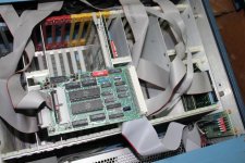
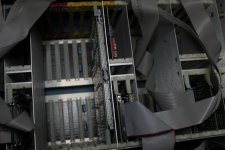
I don't know about the enclosures. They look like off the shelf stuff but Rockwell could have used them. The boards inside are either STD bus or Euro bus ( I think that is what they are called ). The cables on the back are likely for pods that are likely gone.
I have a similar development system but mine would have had a external floppy drive and some special monitor ( most likely with the drive in the same enclosure ). Mine has a 6502 processor board that I expect to just connect to a RS232 serial ( the processor boards have RS232 drivers ). Mine didn't use BASIC but a house setup Forth based on Fig Forth. I've made some modifications to the code on mine to boot to serial but not had time to try it out.
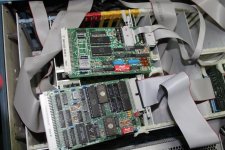
I see you have a full set of manuals. I hope one of them is for the processor board ( I can't read the fine print ). If so, I'd really love to get a copy of it. There are a lot of configuration jumpers on the CPU board.
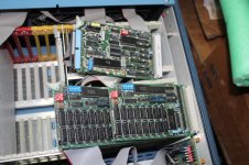
My unit uses the Euro bus boards. These are hard to get additional boards for but the STD bus boards are more common in the US. Still, I have more than enough RAM ( I have 64K plus 32K on the ICE boards ). It is possible to bank the boards so one could have more than 64K RAM. There is a separate ICE interface board in mine but isn't of much use without the POD at the end of the cable and some software to load.
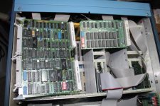
These are the same boards that they sold for industrial use so they are quite high quality.
If you like, I can give you a copy of my modified Forth. I assume the BASIC it has is related to the BASIC used on the AIM65. Looking at the Forth I have, it looks similar to the AIM65's Forth. If you get any disk with it, it would be great to make copies. The disk would have things like the assembler and debugger stuff.
The CPU likely uses those nasty 24 pin 8K byte EPROMs. Not many programmers handle them. One can always make an adapter to the more standard larger 28 pin chips.
Dwight
 
The (E) in the name indicates the Euro type boards. These use a triple row pin type connector as compared to the STD bus that uses an edge connector. Both types of boards would use the same manual. The SBC is the RM65-1000 manual!!
Dwight
 
The pictures aren't great. These are the manuals with this unit.

- Floppy Disk Controller (FDC) Module User's Manual
- General Purpose Input/Output (I/O) and Timer Module User's Manual
- RM65-0110 Input/Output ROM User's Manual
- 8k Static RAM module User's Manual
- 16K PROM/ROM Module User's Manual
- RM 65 Run-time BASIC User's Manual
- Single Board Computer (SBC) Module User's Manual
- 32K Dynamic RAM Module User's Manual
- Asynchronus Communications Interface Adapter (ACIA) Module User's Manual

The AIM 65 comes with:
- Math Package User's Manual
- BASIC Language Reference Manual
- Monitor Program Listing
- User's Guide
- PROM Programmer and CO-ED User's Manual


I will certainly scan whatever is not already scanned.
 
The only manual I know of on the web someplace is the FDC manual. I don't know about the AIM manuals because I've not payed attention to them.
Dwight
 
That was where I'd seen the RM65 FDC manual. It was apparently used with the AIM65 sometimes. I'd assume that they made an adapter to UBC or STD bus, from the AIM65, at sometime.
Dwight

I am hoping the enclosure has at least one multi-slot card cage for RM65 cards like the pictures posted at http://www.vintagecomputer.net/rockwell/R6500/ with the AIM65 expansion port being used to connect to the card cage. I downloaded these pictures and posted here because they are too large to link to.

Rockwell_RM65-8-slot-cage_wMoBd_pic2.jpgRockwell_RM65-Expansion-connector.jpg

If you look closely at one of the pictures above I posted where the back of the enclosure is shown, you can see the expansion port connector for the AIM65 in that mess of ribbon cable.
 
I wonder if it was able to switch between AIM65 controlling the bus and RM65 controlling the bus. The one shown was used with the AIM65 only controlling.
Dwight
 
Here are some pictures of my machine:
The last picture is looking down into the rack. Notice that there are two long UCB strips. The large card strattles the two busses. The RAM card is 8Kb of high speed static RAM. 1112 shows the SBC and a serial card. The 1113 is two 32Kb DRAMs and a floppy disk card. 1114 a parallel I/O using 6822s.
In 1114 you can see a board in the corner with LEDs and switches This goes to a parallel port of the SBC. All the cables shown go the the back panel. The front panel has a 24 and 28 pin zip but I have no board connected to them.
Dwight
 

Attachments

  • IMG_1114.jpg
    IMG_1114.jpg
    98.7 KB · Views: 4
  • IMG_1113.jpg
    IMG_1113.jpg
    98.2 KB · Views: 4
  • IMG_1112.jpg
    IMG_1112.jpg
    99.9 KB · Views: 4
  • IMG_1111.jpg
    IMG_1111.jpg
    100 KB · Views: 3
  • IMG_1110.jpg
    IMG_1110.jpg
    92.9 KB · Views: 3
Last edited:
Hi Dwight,

The system came. Here are a couple of pictures. I have a link to the manuals below (adding manuals as I scan them).

AIM 65 1.jpgAIM 65 2.jpgAIM 65 3.jpg

It has a slightly different AIM 65 interface than the one shown in the thread. I will take better pictures of all of the components. Sadly, no SBC in the card cage but that's okay.

Manuals:

http://vintagecomputer.ca/files/Rockwell/AIM65/
 
Last edited:
It looks like the cards you have from the bottom are:
32K RAM
Bus interface
Floppy controller
Serial card??

The top card doesn't look like my serial card or a parallel card. I'd be curious what it is. It looks like some of the wires go off to a switch board in the back, similar to my parallel I/O card.
Your cards look to be STD bus cards. Those will be easier to get additional cards for.
It does look like it intends to use the AIM65 as the bus master. That is good because there are a lot of good ROM sets for the AIM65, even though you didn't get the SBC card for the rack.
Thanks for posting the manual.
Dwight
 
It looks like the cards you have from the bottom are:
32K RAM
Bus interface
Floppy controller
Serial card??

Not sure about the RAM size or the serial card at this point. I haven't compared the cards to the manuals I have yet but the "serial card" may be a General Purpose I/O and Timer card (parallel) because I have that manual that I am also scanning. The small ribbon cable goes off to a small breadboard circuit, not a switch. I'll have to take a picture of that. These are all Eurocard format cards. I'll have better pictures soon.
 
My parallel card has the connectors at two levels, similar to the bus card you have. See my pictures #1, with the two 6522s on it.
Maybe yours is a mixed card with parallel and serial or something???
Before doing to much use a sharpie to mark the connectors and locations of offset like the floppy. Once you start pulling thing apart, to look at address selects, it will be difficult to reinstall things.
Look at my picture #2. That has two 32K RAM cards on it. It would be interesting to see where yours is mapped, compared to the AIM65 mapping.
Dwight
 
I guess they pushed the eurocard bus board for development use. The are more rugged but cost a little more than STD boards.
A picture of the top card would be interesting, as well as some closer pictures of the bus interface cards.
No rush, I'm just real curious.
Dwight
 
My parallel card has the connectors at two levels, similar to the bus card you have. See my pictures #1, with the two 6522s on it.
Maybe yours is a mixed card with parallel and serial or something???

Have a look at this manual here: http://vintagecomputer.ca/files/Roc...nput Output and Timer Module Users Manual.pdf
I am fairly certain this is the card but it's not in front of me. I already have pictures, I just haven't posted them yet. I may only have the 8K SRAM card as I have that manual and the 32K DRAM card manuals.
 
There is nothing about the RM 65 edge connector version boards that is STD Bus.

RM 65 Edge Connector version:
Width: 3.9 inch
Length: 6.5 inch
Edge Connector: 72-pin, 0.100 inch spacing

STD Bus:
Width: 4.5 inch
Length: 6.5 inch
Edge Connector: 56-pin, 0.125 inch spacing
 
Back
Top