Finally got it to work in my IBM 5155 due to a faulty SPLD!
Finally got it to work in my IBM 5155 due to a faulty SPLD!
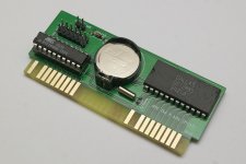
I ordered one of these cards to put in my IBM 5155, where I asked for the SPLD to be programmed to port 70h. After further research, it would conflict with port 70h in an IBM, so I should have ordered it as port 240h.
When it arrived, I used my TL866II+ programmer and reprogrammed the SPLD to port 240h from https://github.com/spark2k06/hardware/blob/master/RTC8088/SPLD/RTC8088_240h.jed, with the encrypt bit unchecked, which verified correctly.
Unfortunately, it did not actually work. I ran a continuity test on the PCB, which seemed to be fine. I tried David's Clock utility as above, then I also tried https://github.com/wilco2009/RTC_micro8088 that spark2k06 suggested.
I then spent all day trying to get it work. I reprogrammed it with the port 240h code about 15 times with different voltages. I even swapped the Dallas chip for a DS12887 (the one with a built-in battery), and tried the card in another computer using the port 240h port. I again checked my multimeter for continuity, which passed.
spark2k06 helped me out on a private thread on Tindie. There could be a conflict with port 240h with another card, and don't try using slot 8. Also, don't try to use a DS12887 with a built-in battery, none of them will probably work today. (The one I tried has a batch code of 0523A2 114326 from a 486 motherboard that was still working from 2019.)
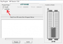
Although I did not tell spark2k06 which programmer I used, he has the same as me, which is a TL866II+, where he had no problems with it. He said that if it is the one I use, it is very important to deactivate the "LOCK Bit" checkbox, otherwise nothing works.

I noticed that the screenshot had a few differences. I updated the Xgpro software and firmware to v10.5, and tried with the lock bit off. I removed all the cards from my IBM, except the CGA, floppy, and XT-IDE, where the XT-IDE operates on 300h. Unfortunately, it still did not work.
I do have a bit of engineering experience, therefore I was able to modify https://github.com/spark2k06/hardware/blob/master/RTC8088/SPLD/RTC8088.pld for 240h, which generated the same output as https://github.com/spark2k06/hardware/blob/master/RTC8088/SPLD/RTC8088_240h.jed. There is no PLD file for 240h on GitHub, so I had to make my own.
GAL16V8 ; Works with GAL16V8B and ATF16V8B
RTC8088 ; RTC 8088, Production version 1
A0 A2 A3 A4 A5 A6 A7 A8 A9 GND
IRQ IOW IOR RTCALE RTCWR RTCRD AEN IRQOUT NC VCC
/IRQOUT = IRQ
/RTCRD = /IOR * A0 * /AEN * /A2 * /A3 * /A4 * /A5 * A6 * /A7 * /A8 * A9
/RTCWR = /IOW * A0 * /AEN * /A2 * /A3 * /A4 * /A5 * A6 * /A7 * /A8 * A9
RTCALE = /IOW * /A0 * /AEN * /A2 * /A3 * /A4 * /A5 * A6 * /A7 * /A8 * A9
DESCRIPTION
This is the logic of decoding the port address and signals used by the RTC based on DS12885.
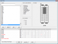
This PLD file enabled me to create a custom logic test for the on the SPLD, using addresses 70h and 240h, and I think pin 14 RTCALE could be faulty.

spark2k06 was pleased with my research above. He would not be surprised if the SPLD was damaged, it had already happened to him with others, but the failure occurred during programming. In my case, the fault was invisible to him because it appeared to program correctly, therefore he would now always do a test as above, and thanked me for sharing my idea.
Further progress had been made.
Because pin 19 of the SPLD is NC, I therefore remapped it to be RTCALE and made pin 14 NC instead. I bridged a wire between the two pins and swapped the pins round in the source.
A0 A2 A3 A4 A5 A6 A7 A8 A9 GND
IRQ IOW IOR NC RTCWR RTCRD AEN IRQOUT RTCALE VCC
I placed it in my full setup IBM 5155 and it works with this workaround, therefore I confirmed that pin 14 is bad! We had both learnt from this, where my case is unique so far. Therefore, spark2k06 gave me a refund for the damaged SPLD.

On the RTC card, a thin bridge wire between pins 19 and 14 is hidden between the SPLD and IC socket. I also desoldered the Dallas IC socket using ChipQuik and soldered the Dallas IC directly to the PCB, so that it does not interfere with the commonly available CompactFlash IDE bracket that sits directly above it. All slots are in use.
spark2k06 gave me permission to publish my research on this forum. Remember, my case had been unique so far, that it did not fail during programming but the SPLD was still damaged. This is to warn potential future users, especially those who build it on their own, that this can happen.
Therefore, if you build your own board, and that the Xgpro programmer software programmed and verified successfully, but the card does not actually work, do a logic test on your SPLD because it could be faulty!
Finally got it to work in my IBM 5155 due to a faulty SPLD!
I ordered one of these cards to put in my IBM 5155, where I asked for the SPLD to be programmed to port 70h. After further research, it would conflict with port 70h in an IBM, so I should have ordered it as port 240h.
When it arrived, I used my TL866II+ programmer and reprogrammed the SPLD to port 240h from https://github.com/spark2k06/hardware/blob/master/RTC8088/SPLD/RTC8088_240h.jed, with the encrypt bit unchecked, which verified correctly.
Unfortunately, it did not actually work. I ran a continuity test on the PCB, which seemed to be fine. I tried David's Clock utility as above, then I also tried https://github.com/wilco2009/RTC_micro8088 that spark2k06 suggested.
I then spent all day trying to get it work. I reprogrammed it with the port 240h code about 15 times with different voltages. I even swapped the Dallas chip for a DS12887 (the one with a built-in battery), and tried the card in another computer using the port 240h port. I again checked my multimeter for continuity, which passed.
spark2k06 helped me out on a private thread on Tindie. There could be a conflict with port 240h with another card, and don't try using slot 8. Also, don't try to use a DS12887 with a built-in battery, none of them will probably work today. (The one I tried has a batch code of 0523A2 114326 from a 486 motherboard that was still working from 2019.)
Although I did not tell spark2k06 which programmer I used, he has the same as me, which is a TL866II+, where he had no problems with it. He said that if it is the one I use, it is very important to deactivate the "LOCK Bit" checkbox, otherwise nothing works.

I noticed that the screenshot had a few differences. I updated the Xgpro software and firmware to v10.5, and tried with the lock bit off. I removed all the cards from my IBM, except the CGA, floppy, and XT-IDE, where the XT-IDE operates on 300h. Unfortunately, it still did not work.
I do have a bit of engineering experience, therefore I was able to modify https://github.com/spark2k06/hardware/blob/master/RTC8088/SPLD/RTC8088.pld for 240h, which generated the same output as https://github.com/spark2k06/hardware/blob/master/RTC8088/SPLD/RTC8088_240h.jed. There is no PLD file for 240h on GitHub, so I had to make my own.
GAL16V8 ; Works with GAL16V8B and ATF16V8B
RTC8088 ; RTC 8088, Production version 1
A0 A2 A3 A4 A5 A6 A7 A8 A9 GND
IRQ IOW IOR RTCALE RTCWR RTCRD AEN IRQOUT NC VCC
/IRQOUT = IRQ
/RTCRD = /IOR * A0 * /AEN * /A2 * /A3 * /A4 * /A5 * A6 * /A7 * /A8 * A9
/RTCWR = /IOW * A0 * /AEN * /A2 * /A3 * /A4 * /A5 * A6 * /A7 * /A8 * A9
RTCALE = /IOW * /A0 * /AEN * /A2 * /A3 * /A4 * /A5 * A6 * /A7 * /A8 * A9
DESCRIPTION
This is the logic of decoding the port address and signals used by the RTC based on DS12885.
This PLD file enabled me to create a custom logic test for the on the SPLD, using addresses 70h and 240h, and I think pin 14 RTCALE could be faulty.

spark2k06 was pleased with my research above. He would not be surprised if the SPLD was damaged, it had already happened to him with others, but the failure occurred during programming. In my case, the fault was invisible to him because it appeared to program correctly, therefore he would now always do a test as above, and thanked me for sharing my idea.
Further progress had been made.
Because pin 19 of the SPLD is NC, I therefore remapped it to be RTCALE and made pin 14 NC instead. I bridged a wire between the two pins and swapped the pins round in the source.
A0 A2 A3 A4 A5 A6 A7 A8 A9 GND
IRQ IOW IOR NC RTCWR RTCRD AEN IRQOUT RTCALE VCC
I placed it in my full setup IBM 5155 and it works with this workaround, therefore I confirmed that pin 14 is bad! We had both learnt from this, where my case is unique so far. Therefore, spark2k06 gave me a refund for the damaged SPLD.

On the RTC card, a thin bridge wire between pins 19 and 14 is hidden between the SPLD and IC socket. I also desoldered the Dallas IC socket using ChipQuik and soldered the Dallas IC directly to the PCB, so that it does not interfere with the commonly available CompactFlash IDE bracket that sits directly above it. All slots are in use.
spark2k06 gave me permission to publish my research on this forum. Remember, my case had been unique so far, that it did not fail during programming but the SPLD was still damaged. This is to warn potential future users, especially those who build it on their own, that this can happen.
Therefore, if you build your own board, and that the Xgpro programmer software programmed and verified successfully, but the card does not actually work, do a logic test on your SPLD because it could be faulty!
