Elar
Member
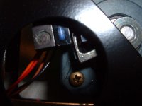
Actually, Track 0 is set by optical sensor. The white part/screw acts as a mechanical emergency stop in case optical sensor fails for some reason. It prevents heads going "over the edge".
Actually, Track 0 is set by optical sensor. The white part/screw acts as a mechanical emergency stop in case optical sensor fails for some reason. It prevents heads going "over the edge".
")
Note that because the stepper motor and head arm are untouched, the tracks will be written in exactly the same locations on the platter. The positioning of the track 0 sensor is a crude adjustment that affects which of those tracks is defined as track 0. And so your goal will be to adjust the sensor so that the track that's currently track 1 becomes the 'new' track 0.Thanks for the info. If this is the case, then the only way to alter Track 0
position is to modify the part of the arm that is 'picked up' by the sensor,
or physically move the sensor (which would be a pain).
) ) of the stepper motor- I just wasn't sure in what direction the calibration point (== track 0) should be moved. I assume more inwards to avoid the edge of the platter, and that would be to make the drive think that it is at track 0, while it is at the (initial) track 1. That again would mean to make the arm longer, to trigger the sensor in the former track 1 position.That didn't helped for long.
But I might find out why it's not Okay.
I saw Jorg's pic of ST-412's motor:

That block is there for a reason, and the only reason I can see is to adjust the sensor (I think it's a hall effect sensor rather than an optical sensor).
HALL EFFECT: See http://en.wikipedia.org/wiki/Hall_effect_sensor
Track 0 sensor is optical. Check the manual:
http://www.bitsavers.org/pdf/seagate/ST412_OEMmanual_Apr82.pdf
Wow, the original manual, now thats valuable info ! Thanks a lot for posting that link
It looks like my will work too.
I've done the same as Mikey and drive worked just fine after 'cold' power up.
I'll see how it will work next day.
If it will work, problem was in positioning.
.
Mikey and others, there is wat to change pisition of sensor.
It's much more realible.
Just get that screw out and put something under sensor and you've got it higher.
I think that you understand this
No, that's a bad idea...
It move track 0 back.