• Please review our updated Terms and Rules here

Sinclair spectrum +2 gray model video issues (not transistor related, probably)

Divarin

Veteran Member
Joined
Mar 9, 2019
Messages
565
Location
Cleveland, OH
Hi all. I've had a Sinclair Spectrum +2 (gray model) in my collection and haven't been able to use it due to not being able to get reliable video out of it.
First off, I am aware of the manufacturing issue where transistors were installed backwards and have already reversed the one transistor that's related to video output.

Second, for reference I am in the US (NTSC land) but I do have one monitor (a Marshall Lynx) that will work with both NTSC and PAL signals. I also have another PAL monitor (it's an LCD tv/monitor designed for use on a piece of Nautilus exercise equipment).
The Lynx has the following inputs available: VGA, Composite, DVI, YPrPb, S-Video
The Nautilus has the following inputs available: VGA, Composite, RGB, S-Video, RF (PAL only)

Now here's what I have tried:
I picked up an RGB to SCART cable from Retro Computer Shack.
I don't have any SCART input so...

First I picked up a cheap SCART to Composite adapter, which I now know isn't doing any kind of active translation it's just taking the composite signal (if there is one) and passing it along. If I hook this up then I get an almost black signal but if you turn the brightness way up and squint you can see the computer is working. I'm assuming either there is no composite coming out of the computer on this port (given the port is labeled RGB that makes sense) or the scart cable from Retro Computer Shack just didn't wire it up.

As for the Nautilus I tried to connect the RF output of the spectrum to this monitor's RF input but unfortunately I don't have the remote for the monitor and it seems that it's impossible to program the channels without it so I'm stuck on channel 1, and I don't see anything there. I did also try connecting the computer to an NTSC tv and go through the channels thinking maybe I'd see something even if it was all messed up but didn't see anything. I really don't know what channel I'm supposed to be tuning into, but regardless I'd prefer not to use RF anyway if I can avoid it.

Then I picked up a SCART RGB breakout cable which has BNC connectors for Red, Green, Blue, Yellow (presumed composite) and two RCA connectors: Red, White (I presume this is right/left audio)
I connected the Red, Green, Blue to the Lynx's Pr, Y, Pb jacks (respectively) and got no signal.

Then I figured that maybe the Lynx is trying to sync on green but there's no sync on either of these cables, only on the composite so I connected the Yellow to the Y jack and got a purple flickering picture (computer appears to be running fine)

Also, there is a 4th BNC connector on the Lynx near the Y Pb Pr jacks but has no label. I thought maybe this is for external sync so I tried connecting the yellow cable there but this didn't do anything. Maybe it's not wired up? I don't know why they put a BNC connector there if it doesn't do anything.

So, my next best guess is that somehow I need to get the sync signal mixed in with the green and pipe that into Y but if the only sync is on the composite won't that cause a lot of issues with Red, Green, Blue, and Sync all being mixed together?

That's where I am right now.
 
As the Spectrum +2 outputs RGB rather than YPrPb, I would focus on trying to get this working with RGB, which the Nautilus appears to have. RGB requires obviously R, G, B, GND and Sync, sometimes Composite Sync (as with SCART) and sometimes separate syncs, as you have on the VGA interface for example. The other good thing about RGB is that it completely bypasses any notion of PAL or NTSC since these are ways of encoding the colour signal onto a video signal and then unencoding it at the other end. If you are using RGB this is irrelevant because the colour signals are never encoded and do not need to be decoded. All that matters is whether your display can work at the typical 50Hz PAL frame rate rather than the typical 60Hz NTSC frame rate.

On the DIN video output connector on the Spectrum, pin 1 outputs Composite video and this is the signal you would use for Sync if you were driving a SCART input - with the SCART display set to RGB mode the display side circuitry uses the R, G, B input signals and uses only the sync portion of the composite video signal as Composite Sync. If the RGB input of the Nautilus is 'Analogue' rather than TTL-Level, you should try using the Composite-Video output from the DIN socket pin 1 as composite sync in to the Nautilus.

However, the Spectrum also outputs a TTL-level composite sync signal on pin 4 of its video output connector, and maybe this is the sync signal that your Nautilus needs instead.

Do you have any details of the RGB input of the Nautilus - if it isn't a SCART connector, what is it instead, something like a 9-way sub-D?

Hmm so it looks like the yellow cable on the scart breakout is basically sync only? In other words if I plug that into a composite input I get a signal (the "no signal" warning goes away) but no video. I suspect this is the same really dark video I was seeing before when trying to use the scart to composite adapter and hooking it up to a CRT (Commodore 1702) instead of the Lynx.

The RGB inputs on the nautilius are RCA. I haven't tried using them yet. Looking to do that now I realize I have a whole ton of RCA to BNC adapters but exactly 2 BNC to RCA. So to hook this up to the nautilus I'd need at least one more of those.

I guess I'd be fine with just composite but for some reason other than a sync I don't see a signal there.

EDIT: just tried the yellow cable from the breakout on the 1702, as suspected it is exactly the same as when I was trying to use the bnc to composite adpater. There is a faint dark picture there.
 
Last edited:
I can't really address your question regarding transistor changes as I'm not familiar with the reason why you would be altering anything away from the way the machine was originally assembled.

Can you explain to me a little more what you mean by 'SCART Breakout'? There is no purely Sync signal on a SCART interface - if we are talking about a SCART output on a VCR or DVD for example then the only sync-like signal coming out of that is Composite Video. It is up to the SCART device at the other end whether to use the Composite-In it is receiving as whole composite video (when in Composite input mode) or to only use the Sync portion of the composite video as composite sync (when in RGB input mode). The SCART interface does not have a distinct / separate composite sync signal input.

As said earlier, the Spectrum video-out socket has Composite video out on pin 1, and TTL - level composite sync out on pin 4.

The RGB RCA inputs on your Nautilus are presumably R, G, B and (?) Do you have the exact model name / number of the Nautilus there?
 
And sorry, to explain further... I also have a grey Spectrum +2 which I have owned from new and RGB output works fine to my Philips RGB video monitor, which has a SCART input. I have never even had it apart, and I have never needed to rearrange any of the transistors.

The R-G-B outputs from the Spectrum are TTL-level which is a bit 'strong' for the R-G-B inputs on a standard video monitor, so the lead contains resistors in the R-G-B lines to attenuate the high output levels from the Spectrum before sending them to the analogue R-G-B inputs on the monitor. In this case it is the composite-out signal from the Spectrum which is taken to the Composite-In pin on the monitor's SCART socket.

It's difficult to know without more info whether your Nautilus display expects TTL level RGB and Sync or whether it expects video-level analogue RGB and Sync.
 
Hmm I'm trying to use the lynx monitor if I can even if it's only with composite because I don't really have room for another monitor setup. But I can use the nautilus monitor for testing.

This is the breakout cable: https://www.amazon.com/gp/aw/d/B08JGCXKRT

I've read from multiple sites that on the gray model some of the transistors were installed backwards causing either rgb or composite output to not work.

It's been probably a year since I flipped the T4 transistor in mine and only now have things settled down enough for me to pursue trying to get this going. But IIRC I did try the composite output prior to changing that transistor around.
 
I've read from multiple sites that on the gray model some of the transistors were installed backwards causing either rgb or composite output to not work.

As I mentioned, I have owned mine from new in about 1986(?) and I have never had to take it apart or reposition transistors for any reason.

SCART RGB obviously requires that the R, G and B signal lines all work but ironically also requires there to be Composite Video output from which it can harvest the sync. As you probably realise there also needs to be a fully formed composite video signal for the RF-Out (TV) signal to work, because the same composite signal is fed to the input of the RF modulator.

I always aim to use RGB rather than composite (cleaner, better quality) and it is possible that maybe I also got the same 'black' composite signal as you but I just didn't worry about it because I was only concerned with getting RGB to work. To be honest though I am sure I would have remembered that. However my +2 is due a check over so I may try to get it down and check this out some time in the next few days.
 
I've looked at your breakout cable linked to in #7 - I take it that as well as this cable you also have a Spectrum DIN to SCART male plug cable which you are connecting to the female socket on this breakout cable?

If so, it looks to me as though Composite should be coming out of the YELLOW cable on the breakout cable, as this is described as 'Sync'. I don't suppose you have an oscilloscope?
 
I've looked a little bit further into this: The diagram (for anyone following) is here:-


I see that TR1 / TR2 / TR3 are the composite video buffer / drivers for the ULA to modulator path, but composite-out to the monitor socket has its own buffer transistor which is TR4. Certainly if that transistor was in the wrong way around it would affect the composite video output to the monitor-out socket. Now, the question is whether your TR4 was originally the right way around before and is the wrong way around now, or vice-versa?
 
The other thing to note is the 'P and 'S' links in that circuit area. For Composite Out to appear on the DIN socket pin 1, LK4 has to be fitted and LK2 not fitted, if I am reading the diagram correctly. You haven't said where your +2 came from but it might be an idea to see whether the links are set in the 'P' or 'S' position in your example.
 
Yeah I have a din to scart cable picked up from retrocomputershack.com.

I do have an oscilloscope, it's an old analog crt one but it works.

I am about 75% sure I did try to connect the composite output before reversing T4 but that was about a year ago so it's possible that I'm not remembering correctly, I can try to put it back the way it was just to be sure.

I agree RGB is much nicer than composite and if I can I'd like to use the YPbPr ports on the lynx monitor.
 
Did a little more research today and it appears the suspect transistors are 2N3904's so today I plan on looking the board over, identify which transistors are 3904's and try swapping them around (I know TR4 was one of them but that's the only one I reversed).
I'll also order some more BNC to RCA adapters so I can try connecting the RGB to the Nautilus monitor.
 
If you have an oscilloscope you can use that to do most of your diagnosis from outside of the machine without even taking it apart. An analogue scope is absolutely fine for this. If you start twirling transistors around in semi random fashion, even for only four transistors that makes 16 possible combinations of turned or not turned and only one of those 16 possible combinations is right. I'm at work just now so I can't really walk you through it just at the moment, but if you wait I will suggest some measurements with the scope later on, or anyone else who is less busy can do so sooner.

As I mentioned, it may be the positions of the 'P' and 'S' links which are the actual problem, not the transistors.

Be aware that TR1, TR2, TR3 are only involved in the Composite Video Feed to the RF modulator, and TR4 is only involved in the composite video feed to the video-out socket.

You mentioned YPbPr, I am certain that the Spectrum does NOT output video in this format so there is little point in trying to get that to work.
 
Last edited:
If you have an oscilloscope you can use that to do most of your diagnosis from outside of the machine without even taking it apart. An analogue scope is absolutely fine for this. If you start twirling transistors around in semi random fashion, even for only four transistors that makes 16 possible combinations of turned or not turned and only one of those 16 possible combinations is right. I'm at work just now so I can't really walk you through it just at the moment, but if you wait I will suggest some measurements with the scope later on, or anyone else who is less busy can do so sooner.

As I mentioned, it may be the positions of the 'P' and 'S' links which are the actual problem, not the transistors.

Be aware that TR1, TR2, TR3 are only involved in the Composite Video Feed to the RF modulator, and TR4 is only involved in the composite video feed to the video-out socket.

You mentioned YPbPr, I am certain that the Spectrum does NOT output video in this format so there is little point in trying to get that to work.

Yeah I am at work right now as well so I'm in no hurry to try anything.
I'm not very skilled at using my oscilloscope but I have been able to make some use of it.

I'm not really sure what you meant by the 'P' and 'S' links, maybe later you can explain that.
 
Did a little research, let me see how close I've come.

Pin 5 on the RGB connector can be either: vsync or -12 volts depends on if it's set up for Péritel or Standard. I haven't heard of Péritel before but I'm reading up on it now. This would explain why you asked where the computer came from. I bought it from a guy on Ebay who is based in Egypt and sells a lot of vintage computer gear, tifsasa-0.

I've purchased a few other things from him before including a PAL c64 and vic 20. Anyway given that, there is a very good chance it did come from an area where it was configured for Péritel.

My guess about the oscilloscope is you want to see if pin 5 is a constant voltage (-12) or if it actually has a sync signal on it.
 
And also pin 1, which can have either steady voltage or composite video coming out of it, depending on the positions of those links. Obviously, you need the links set for composite to come out of pin 1.
 
There does seem to be some kind of a sync signal on the yellow wire on the breakout cable just in how the monitors I've hooked it up to respond but I'll get a better look at it on the scope later.
 
Well, at least that breakout cable is going to make it super easy for you to plug each of the signals into the scope :)
 
composite02.jpg
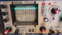
Here's what I'm getting on the composite wire (the yellow wire)
I also tested this without the cable by plugging a paperclip into pin 5 and connecting the scope probe to that. In both cases I used the shielding on the can around the RF modulator for the ground.
It looks like a signal is present, which is consistent with the fact that monitors I've tested this composite output with seem to react as if a valid sync is present.

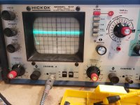
Here is pin 1:
pin1.jpg
There's some kind of signal there.

Strangely I tried to trace the connections between pins and the various wires on the breakout cable but I couldn't get continuity with my multimeter between anything, even the ground. Yet there are signals coming through.

If the yellow cable is pin 5 that could be composite sync only and composite video (hopefully with sync), which I think is pin 1 (just going by the diagram on page 4 here), who knows if that's coming out one of these wires on the breakout or not. I guess I can just try them all and see. I don't see any 12 volts or higher on any pins so should be safe.
 
Back
Top