• Please review our updated Terms and Rules here

Strange CRT Behavior....

3pcedev

Veteran Member
Joined
Jun 8, 2014
Messages
735
Location
Australia
Hi all,

After about 12 months I have finally found a free day to have a look at my Olivetti M24 (AT&T 6300) colour display.

I bought the colour CRT (which is an Olivetti branded one) a while ago and only briefly tested it. At the time I noticed I couldn't adjust the brightness/contrast low enough, and you could always see the raster pattern no matter what.

Today I thought I would have another go and see if I could narrow down the problem. What I found was something I had never observed before.

When the screen is predominantly black (i.e. at the DOS prompt) you can easily adjust the brightness and contrast to the correct levels.

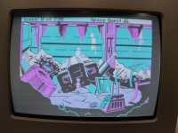
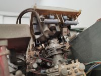
As soon as the screen begins to fill with an image (irrespective of colour) the brightness 'ramps up' across the whole display. The ramping is almost like a capacitor charging, the image appears perfect for about a second then you see the brightness 'ramp up' over the course of another 1-2 seconds. Depending on how much of the display is filled, the brightness increases in proportion. If enough of the display is filled, its so bright that the raster is clearly visible. I have attached a few images for reference.

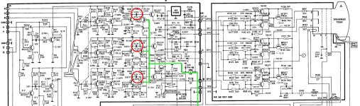
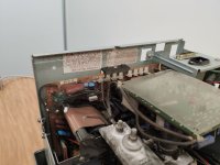
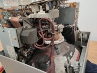
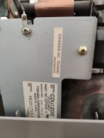
Before I rip into the display and blindly look for faults, any pointers on what could cause this behavior? Unfortunately I don't have any circuit diagrams for this particular model; it's different from the AT&T counterpart and no matter how much I have searched I come up empty.

Thanks for the help!
 

Attachments

  • IMG_20220415_165136.jpg
    IMG_20220415_165136.jpg
    1.8 MB · Views: 18
  • IMG_20220415_165437.jpg
    IMG_20220415_165437.jpg
    1.5 MB · Views: 17
  • IMG_20220415_165410-small.jpg
    IMG_20220415_165410-small.jpg
    376.6 KB · Views: 19
I've seen this before, it made me nervous using it. Last time I saw it, CRTs were worthless, just moved on to the next one. Another thing that may be related is the image getting bigger when the brightness increases. Unfortunately I don't really know what causes it. Flyback, some capacitor? IDK.
 
Looks like an issue related to power supply--when the screen gets brighter, the drain on the PSU is higher and voltage can sag. A quick check on voltages might indicate something in this vein.
Didn't Hantarex make most of the M24 displays? You might be able to find something similar using that as your search criterion.
 
As you can see from the image, what is happening is that as the average video level is increasing, so is the black level, to the extent that the vertical retrace lines can be seen.

If this ramping up of brightness was independent of the video input signal and its level, then likely that would indicate a fault in the retrace blanking circuit, but is not as likely, so that shifts the likely location of the fault to the DC restoration circuitry (which also goes by the name the "Black Level Clamp"). However the retrace blanking circuitry with a fault making it partially active during scan time could cause similar trouble.

The black level clamp (which is applied to all three guns) is designed so that the DC axis of the video signal presented to the gun is stable. The reason it is not stable is that any design of the video amplifiers which pass the signal via a coupling capacitor, the DC component is lost, only the AC component coupled, so the black level then wanders around with contrast changes.

The overall DC axis that the CRT ends up with is essentially set by the user via the brightness control setting, so that "black" is just when the beam fails to illuminate the phosphor. Although the physical control itself might be in the grid circuit, and the CRT gun drive with a black level clamp in the cathode circuit, the result is the same. So that as the video dive level increases, the value of black stays at the same value, regardless of the images contrast. Typically, if this circuit malfunctions, as the contrast increases the black gets forced blacker than black. However, with the circuit arrangements it can sometimes go the other way.

Generally the the black level clamp relies on the principle of discharging a capacitor in the video signal pathway with a transistor, to a fixed potential and doing it at line rate (using H pulses to switch the transistor during or near the end of H flyback).

However, there is another scenario. In some designs of the video stages leading from the input circuit to the CRT's gun, the design was direct coupled (or DC coupled as it is known). In this case black level clamping is automatic, without the need for a black level clamp of DC restorer circuit. This is because the video voltage, corresponding to black, remains at a fixed value regardless of the contrast or video signal amplitude. This circuitry could still acquire a fault though, though probably less likely.

It is difficult without the schematic to provide a specific suggestion. In these cases I copy the schematic out from the set.

Most likely it will be due to a failing electrolytic capacitor, hence that ramping effect, and the most likely physical location will be on the CRT's neck/socket board, because this is where the video amp/gun driver circuits often are and also this area often gets very hot shortening the life of the electrolytic caps there. However again it could be a thermal problem and a drift in an IC, if there is on,e in the video amplifier chain, because often the designs were Class B and they heat up more at higher contrast levels.

I would suggest if you cannot find the schematic, you could initially re-cap that neck board first.

When you work on the VDU, you do not have to discharge the CRT unless you go under the anode (EHT) cap, and you don't need to there for this fault, so simply keep away from that. The CRT's bulb charge is isolated from the CRT's base/gun pins so after the set is turned off you can unplug that socket & neck board and touch those CRT pins without any worries when you are working on the CRT's neck board. The charge remains safely inside the CRT. It pays to leave the set off for an hour or two though, before you work on it, so that other capacitances have discharged.

But, without the schematic it is a "non targeted" repair and it can turn out that the fault resides elsewhere. The only 100% sure way to track the fault down is to have the schematic and go through the circuitry with the scope.
 
Awesome - Thanks for the replies.

I was nervous to keep using the display for fear of burning it out; so I only ran it as long as needed to take those photos.

Chuck - I thought it was a Hanatrex initially; but I can't line it up with a particular model. I'll take the cover off tonight and *maybe* there will be something more printed on the PCB which can be used to identify it. I would like the manual for nothing more than verifying the test points

Hugo - thanks for the detailed reply. That makes perfect sense to me and gives me something to go on. I probably won't 'shotgun' parts at it, I usually desolder each component and test off the board. It's slow; but I like to know exactly what the issue is.
 
The display brightness, at the level it is, won't harm the CRT.

One thing you could try, if it turns out it looks like there is an IC as the video amplifier / gun driver , you could hit it with some freeze spay and see if it affects the black level. Over the years there have been a lot of variations in the designs with discrete transistors in some cases and IC's in others. In the IC case the chip is usually driven by the black level clamp pulse at one of its inputs.

Keep hunting, you may be able to find the schematic.

(As an aside: some early TV sets and some VDU's did not have DC restoration circuits or black level clamping circuits. So in those ones, what typically happens is that with high contrast scenes the black level goes "blacker than black" and the background gets difficult to see. When that is corrected with the brightness control, then on a low contrast scene, the background is too illuminated and the picture looks "washed out". But in the case of your fault, exactly the opposite is happening, suggesting that the reference voltage level that that clamping is adhering to is not stable).
 
Of course in the old days, and I am showing my age here, you had to have the schematic in front of you on the desk.

It was then a simple matter to look with the scope and "Bob was your Uncle", you could fix a circuit in no time.

Now the data that you need comes in pieces as fragments of internet scans. So I guess I'm old school. It is like a mechanic who could reach for some wrench and fix a problem in 10 seconds back in 1960. But 60 years go by and the new age system requires them to put on a blindfold and reach into a canvas bag with 100 wrenches in it, floating in a soup of molasses, and expect them to pull out the correct one, first time.

So I captured the two images and pasted them together in a photo editor to avoid some chaos. See attached.

As I mentioned if there is an AC coupling in the video amplifier design (as shown by the capacitors inside the red circles in this schematic) it requires a clamp pulse, at line rate, to discharge those capacitors (in all three channels), to set the black level. That clamp pulse is taken from the line output transformer and introduced to all three channels as shown by the green highlighting to activate the clamp transistors. The DC reference level is on the emitters of these clamping transistors. So, these are all the parts of the circuitry that should be checked with the scope.

Hopefully your set will conform to the schematic.
 

Attachments

  • CCT2.jpg
    CCT2.jpg
    313.6 KB · Views: 8
Ok, I removed the back cover of the display this afternoon. I was surprised to find it's actually made by Toshiba; a CDU1200 model. I did some googling to try to find a service manual, but came up empty. I don't know if anyone can find / has something similar?

I have attached some photos of the internals. It's filthy, and before I work on it further I need to get out the compressor and thoroughly blow it clean. I would do it now, but the neighbours won't be happy if I start up the compressor at this time of night.

Also thanks for the detailed explanation about the video amplifier design. I have the tools to test all of this; however if there is no service data I am going to have to use some dead reckoning to figure this one out. Ironically this sort of thing is kind of my day job; I spend a large amount of time repairing electronics in (mainly obsolete) scientific instrumentation with limited information.
 

Attachments

  • IMG_20220416_170708_small.jpg
    IMG_20220416_170708_small.jpg
    187.6 KB · Views: 10
  • IMG_20220416_170712-small.jpg
    IMG_20220416_170712-small.jpg
    243.8 KB · Views: 10
  • IMG_20220416_170724_small.jpg
    IMG_20220416_170724_small.jpg
    184.8 KB · Views: 10
  • IMG_20220416_170747_small.jpg
    IMG_20220416_170747_small.jpg
    218.2 KB · Views: 9
As I mentioned, the electros on the CRT neck board tend to fail first. You might "get lucky" and find the defective one/s with an ESR meter, with in circuit testing. You probably have and ESR meter already, if not I would recommend the type that uses a low amplitude test pulse (rather than a 100kHz sine wave). A very good one, designed by Bob Parker is available from Altronics as a kit:


They also are available assembled in a different case and are Called Anatek Blue on ebay;


But I like the kit form with the black case and red LED's and there is plenty of space inside to add back to back diodes to protect it , in case you forget to discharge a capacitor before testing.

To clean it up use an artist brush with very soft bristles and a standard household vacuum cleaner works with the nozzle an inch or two from where you are brushing, better than high velocity air, and you won't bother the neighbors either. You may also need a cotton cloth wet with contact cleaner to help clean some of it it up. A very lightly damp rag (not wet) can also help at times to clean off the soot accumulated on the EHT cables and high voltage components that was electrostatically attracted there over time.

Though, probably the fault is not on the neck board as that is not where the clamp circuitry is. Check to see that the emitter voltage of TR25 (if your set conforms to that schematic) is stable as that is the black reference level.
 
The problem with the number CDU-1200 is that it's an Olivetti part number. For example, you can find the service manual for the CDU-1431 here, but it's a Hantarex product. I did some consulting around 2000 or so for TAIS and I recall that I really liked the monitor on the Infinia, but TAIS couldn't provide any service documentation. Apparently, this is by design.

Do check the two power resistors on the neck board--power resistors have been known to drift with age.
 
Back
Top