• Please review our updated Terms and Rules here

Stunning Motorola 68000 system made by Computer System Associates USA circa 1984

Hi, David. I have one of these, also in a HP briefcase, but mine doesn't work and no display comes up. I bought it at a flea market many years ago, but just pulled it out of storage and was looking around for info and found this thread.
The power supply looks OK, and if I disconnect the SBC the display lights up and responds to keys, so it's probably OK, too. But it looks like I only have one of the PETEBUG PROMs and two copies of the TUTOR U11 PROM, so I could really use a dump of the PETEBUG pair if you get a chance.
 

Attachments

  • DSCF0506.JPG
    DSCF0506.JPG
    537.7 KB · Views: 27
  • DSCF0505_5.JPG
    DSCF0505_5.JPG
    1.1 MB · Views: 29
Hello Gottahack
I have One of these and am in California
Mine is missing the 8751 chip for the display board, It does have both U10 and U11 petebug, I have been trying to get copies of all three versions.
In looking I think the silicon software was a multi tasking OS, but not sure

Would you want to sell the one you have?
Mine is A-001243
From what david has said the 8751 has the security fuse blown so the chip can't be read

Tony
 
Last edited:
Multi-tasking OS would be neat, but not too useful without documentation.

If you could dump the petebug ROMs for me, I could do some work on reverse-engineering the serial protocol. With that, and some work on how to drive the displays, it might be possible to write an unlocked 8751 program that works the same. I only have 8748's in my parts box, but I see there are still some 8751's on ebay.
 
Holy crap that is such a freaking awesome design. I love everything about it, including the wooden side panels.

And those 7-segment LEDs are wonderfully excessive. From the silkscreen on the plastic, apparently they're intended to display the entire 5-word opcode of the longest possible 68000 instruction.
 
Gottahack
The eprom are 2764
Attached is a zip with the 2 bin files.

The AT89S52 which is a EE part has the same pinout as the 8751 so you can use that for testing
I was think that a vampire tap could be used to capture the serial data from both send and receive lines.
 

Attachments

  • petebug.zip
    2.7 KB · Views: 7
Manual for earlier version of the CSA68000 trainer
 

Attachments

  • csa100.pdf
    1.3 MB · Views: 15
  • csa80.pdf
    1.7 MB · Views: 12
  • csa60.pdf
    1.7 MB · Views: 9
  • csa40.pdf
    1.7 MB · Views: 9
  • csa20.pdf
    1.3 MB · Views: 8
  • csa130.pdf
    1.8 MB · Views: 7
Wow, excellent! The memory map looks very different from what the MECB uses, but having docs for the keyboard operations will help a lot. I'll probably be too tied up with work for the next couple of weeks to do a very deep dive into the machine, but I should have plenty of time after that.
 
Hello, could someone write a serial test program to burn to eprom using the ACIA (6850) address
fd0041 acia 1 status register
fd0043 acia 1 data register
fd0061 acia 2 status register
fd0063 acia 2 data register
 
Hello gottahack, have you had any time to work with your system
 
A little bit. I burned the PETEBUG EEPROMs and plugged them in, but the CPU board isn't doing anything except turning on the HALT light. So I'm going to have to debug the CPU card to figure out what's going wrong.
 
Hello Gottahack
Have you tried swapping the eprom locations to see if that works? anything new?
 
That's a great suggestion for one of the easiest mistakes with high/low ROMs. Sometimes it's worth taking ten minutes to rule out the really dumb but easy mistake.

A set full of 4E71 (and a reset vector of 00008080) would be a good thing too, just hook up a scope to some address lines and hit reset. Note that PETEBUG is clearly assembled at $8000, but it looks like it was designed to start up with temporary mirror mapping at $0000, so there shouldn't some other missing ROM.
 
Okay, you guys got my attention enough to start looking deeper into the disassembly. Now that my disassembler supports adding comments, I can concentrate more on the code.

From everything described so far, the 68000 side seems to have RAM at 000000-000FFF, and EPROM at 008000-00BFFF. It also has two 6850 ACIAs at 010041/3 and 010061/3, with the latter connected to the keyboard/display unit.

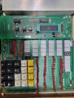
The keyboard/display unit is completely separate, with its own 40-pin MCU. The 68000 just pushes display data to it, and receives codes from the keypad. The keypad is simply 8N1 ASCII, and 7-segment patterns are sent to the display as 0x50, 0x20+index, and two hex ASCII digits of the LED pattern. The digits and rows of 8 LEDs are numbered starting at zero, going left to right in each row.

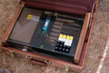
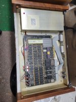
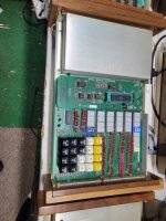
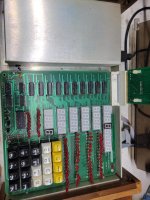
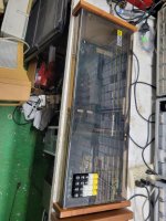
For some reason the "Serial Display Interface" MCU is in a ZIF socket accessible from the top of the "suitcase" model. I'm going to assume that the 68000 board is stacked below it on the suitcase version. I don't even see this board or chip in the "wide" version pictures. The random 7-segment display contents in one of the photographs imply that it might not clear the display on startup.

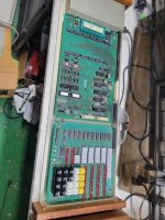
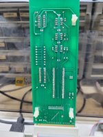
The ribbon cable on top next to the MCU is probably the serial communications, and the edge connector is probably where the MCU drives the display board. On the "wide" version, there is a ribbon cable directly connecting the 68000 board with the display board. For some reason there is an IDP connector on that cable, so maybe it isn't original and was pulled out of random parts for an ebay picture. I don't see any photos of the suitcase 68000 board, so there's not much more that can be determined. It is possible that the wide version doesn't use the serial display interface, but then it would need a different ROM.

If someone has the suitcase version, you should have the MCU dumped so that others can replace a missing one. It will probably be an 8742 or 8732, but none of the pictures show it up close.
 
IF you look at the first page of this thread it has pictures of the added board on top of the display boad which uses a c8751 intel microconroller.
And yes the display board is stacked on top of the 68kecb board
 
I did see those pictures, but nothing was zoomed enough to see the chip type. And it's the "wide" version that doesn't have the MCU board visible.
 
Here is a KIcad project that I started showing how the small serial board connects to the display board
it is not complete and may have a few errors
In a few test I tried I used the AT89S52 which has the same pinout and can be erased and reprogrammed

ON the extra wide version the display board connects to both PIA (6821)
the first is at FD0000 keyboard pia: side a data
FD0001 display pia: side a data
thru FD0007
 

Attachments

  • 68000_display.zip
    1.3 MB · Views: 5

Attachments

  • All_3_Sys.jpg
    All_3_Sys.jpg
    383.2 KB · Views: 20
  • Sys1_tutor.jpg
    Sys1_tutor.jpg
    501.6 KB · Views: 20
  • Sys1_open.jpg
    Sys1_open.jpg
    522 KB · Views: 18
  • Sys2.jpg
    Sys2.jpg
    515.2 KB · Views: 19
  • Sys2_open.jpg
    Sys2_open.jpg
    487.1 KB · Views: 18
  • Sys2_Dspy_top.jpg
    Sys2_Dspy_top.jpg
    496.6 KB · Views: 20
  • Sys2_ser_top.jpg
    Sys2_ser_top.jpg
    558 KB · Views: 19
  • Sys3.jpg
    Sys3.jpg
    452.4 KB · Views: 19
  • Sys3_open.jpg
    Sys3_open.jpg
    479.2 KB · Views: 19
  • Sys2_serial_bck.jpg
    Sys2_serial_bck.jpg
    351.1 KB · Views: 20
I did not notice that in your original post that the suitcase version uses an off-the-shelf Motorola ECB. Oof.

Anyhow, if you can dump the display processor firmware, I should be able to do a good disassembly of it. At least I figured out the protocol thanks to the 68000 code (0x50, 0x20+digit, hex ascii high nibble, hex ascii low nibble), but that won't help if someone has a display board without it. That display board is really the soul of this design, along with the smoke acrylic and wood panels.
 
Hello that is where the problem is the chip that is there is on I wrote some test code a year + ago in trying to figure how the multiplexing of the displays worked
the board was missing the C8751 chip, for testing I went to the AT89S52 since it can just be reprogrammed with out having to use a UV eraser.
I was going to try to write code for it but since my programming skills are just learning I stopped when I got the unit with the side by side boards thinking it would be easier to get going but I am still trying to just get the ACIA going first.
So far I have not had any luck getting the ACIA (6850) talking. not sure if this version of the board ever worked.

Gottahack has one and and the the Person in the AU, has one both of them have the display board micro, but the one in the AU has the security fuse set so it can't be read on a programmer.

I am still searching for other CSA system and Info not much out there.
 
Back
Top