• Please review our updated Terms and Rules here

SuperPET 64k RAM Expansion DIMM Troubleshooting

The basic 8032 configuration seems to be stable and when I add the 6809 system board the intermittent power issues return. I need some advice on how to check out the 6809 board for possible failure points. From the manner in which the failures occur it seems to me to be some kind of power issue, but would like other opinions. I have a DVM that I can use to check voltages etc.
 
OK, so a couple of things come to mind...

The 6502 CPU is removed from the 8032 and plugged into the SuperPET board. There is then a ribbon-cable that connects the SuperPET to the vacated 6502 CPU socket. Examine this ribbon cable and the connectors with a bright light and magnifying glass and 'bell it out' with a multimeter. Check for signs of damage and/or intermittent connection and/or strands of wire shorting from pin to pin.

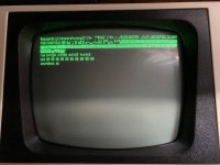
Next would be to plug together the SuperPET as per the documentation and set the switch to 6502 CPU. Can you configure your 3-board set without the memory board?

Next, check the voltages from the three (yes 3) +5V regulators on board the SuperPET.

VR1 and VR2 provide voltage for the logic chips on the SuperPET. You can measure the DC voltage across C20 (VR1) and C6 (VR2). Check the voltage from VR3 at pin 8 of U3 (the 6502 CPU). VR3 is used as a very crude means of disabling the 6502 CPU when the 6809 CPU is running. All of the measurements should be taken with reference to 0V/GND.

I would set your multimeter to read (say) full-scale 10V DC to start with. You should read from +4.75V DC to +5.25V DC. The closer to +5V DC, the better.

If your multimeter has a low voltage AC voltage range, set it to the lowest range and measure at the same three (3) points again. This time we are attempting to see how much AC 'noise' is present. This may be the limiting factor if you have a relatively 'cheap' 'electricians' multimeter.

See how that goes first... Post the results back.

Dave
 
With only the 6809 board configured I see the following readings:
C6 + side = 5 DCV
C20 + side = 4.8 DCV
U3 pin 8 = 0.4 DCV

And nothing on the screen in either 6502 or 6809
 
Last edited:
There is no power supply on the 6502 CPU.

Double check that switch SW2 is in 6502 mode.

Check U13 pin 13. This should be HIGH (> 4V).

Check U13 pin 12. This should be LOW (< 0.8V).

Check U13 pin 10. This should be HIGH.

Check Q2 collector. This should be the voltage across C9 minus approximately 0.7V.

Dave
 
Dave obviously is driving the resuscitation but also check the ribbon cables (cpu and expansion port) are inserted all the way and no bent pins, especially on the 6502 cpu socket and reinserted 6502…. Easily done. Even with no toggle switches connected it should boot to the normal 6502 basic screen.
 
Thank you both for your help troubleshooting this issue.

I have been carefully checking the pins and connections when plugging in he ribbon and power cables.

Yeah my bad on the SW2 setting, it was set for 6809 :rolleyes:

The latest readings are:

U3 pin 8 = 4.94 DCV
U13 pin 10 = 3.38 DCV
U13 pin 12 = 0.24 DCV
U13 pin 13 = 4.99 DCV
Q2 collector = 10.85 DCV
 
>>> Yeah my bad on the SW2 setting, it was set for 6809.

Full marks for owning up :)!

Those readings look fine to me. At least there are Volts on the 6502 CPU now!

Does this now mean that your basic 6502 PET is now working again and (if it is) is it reliable?

Space invaders time...

If it isn't reliable in this configuration - then we can trouble-shoot it.

If it is reliable - then we can move on and add the memory card to see if that has any effect (but still in 6502 CPU mode).

As Andy has said previously - make sure that all of the connectors are straight, clean and 'look good' before connecting them.

Dave
 
The rabbit hole is getting deeper :eek:

So after removing the 6809 board to verify basic 8032 operation I have found that the basic system does have an issue that will spontaneously show itself.

Sometimes when I power it up I see a dark screen, other times the bright raster dot in the middle of the screen and other times it powers up to the basic ready prompt! It may sit at the blinking cursor for some time and then reset/freeze or drop to the monitor with or without garbage characters dumped on the screen.

In addition I can cause the machine to reboot by gently lifting or moving it. I have checked some power readings on the J8 connector and they look fine.

And in addition I will need to find a replacement ribbon cable for the CPU socket harness that connects to the 6809 board. When removing it two of the pins broke, probably due to stress fatigue over the years :( Hopefully not a show stopper for full SuperPet functionality but I'm sure they are not plentiful.

I thought my only issue was the 64k memory banks!
 
Last edited:
No problem. If we know the 8032 is 'misbehaving' then we also know that the SuperPET addon board will also misbehave.

There can be many reasons for the misbehaving like this: Reset circuitry, poor quality IC sockets (of the 'white' sort), intermittently faulty IC component(s), power supply issues, etc.

Do you have the capability for burning 2716 EPROMs at all - or is there someone you know who can? I am thinking now of burning a copy of my PETTESTER into an EPROM and swapping the EDIT ROM (that should be in an IC socket).

My PETTESTER will perform a number of tests on the machine and will quite happily sit there testing DRAM for ever and a day. If the machine fails whilst running my PETTESTER it might lead us in a particular direction.

Let me have a think regarding the best way to proceed...

Dave
 
Dave,

I have an eprom burner and a few 2532 eproms in the parts box. Do I need to find a 2716 or can I use a 2532 for pet tester?

SPet has been sitting at the ready prompt for about four hours now on best behavior LOL

Mayne a temperature thing?
 
It would have to be a 2732 not a 2532. The pinouts are different!

You could use a 2532 at a push - with a little hand-made adapter.

It could be a temperature-related issue. A hair-dryer and some freezer spray could come in handy here if it is...

Dave
 
It would have to be a 2732 not a 2532. The pinouts are different!

You could use a 2532 at a push - with a little hand-made adapter.

Dave,
You are mixing up your EPROMs again.;)

A 2716 or 2532 will work as is. A 2732 will work also without an adapter if the 2K data is put into the upper half of the address space ($0800 - $0FFF).
-dave_m
 
And I looked them up on the darn internet!

There must be a rogue site I keep hitting on. That’s my excuse and I am sticking to it...

Dave
 
I can never remember which is which since I don't work with them every day. Always have to check online (trying to avoid the rouge sites lol).

I will download the PETTESTER binary and burn it. Any particular version or preferred location for download?
 
That's one of my 'trademarks'. That's why it takes me sooo long to do some of my projects. I like to get the documentation right!

However, someone who reads the documentation first?! Go to the top of the class...

My Google drive is the best place and (yes) V04 is the latest.

Dave
 
'V4' Pettest has been a boon to Commodore PET enthusiasts. By using the existing EDIT socket, it is a quick way to test a PET.

By the way, note that one can not use any EPROMs on the PET mainboard in the 6809 Mode due to 'NOROM' incompatibility on pin 21 of EPROMs when pulled down.
-dave_m
 
Yes I posted yesterday about the /NOROM but deleted it .. there are some EPROMs that may work .. but not many and it is difficult to state which ones. In my testing I used a 2k eprom in the $E000- socket. It has a label over it which I don’t want to remove but think it was a MBM2716.

An alternative is to use a 23xx adapter from Retro innovations… I used those in my MultiPET and it responds to NOROM when I have a 2764 eprom installed.
 
Last edited:
An alternative is to use a 23xx adapter from Retro innovations… I used those in my MultiPET and it responds to NOROM when I have a 2764 eprom installed.

Andy,
That's good to know. The adapter must have an inverter somewhere as there is no negative active chip disable on the 2764.
 
Okay, I have burned a 2532 eprom with Dave's pet tester v04 and replaced the edit rom with it.

As with the standard edit rom, it takes several power cycles to get the machine to start the power on reset process. :(

With the pet tester rom in place, the first thing I see on screen is the full character dump, rom checksums and countdown. If the machine doesn't hang, I may also see the dram testing start as well.

I have seen the dram test run as far as pass 0000000a before hanging. For some reason I don't see the initial page 0/1 testing screens but maybe they are too quick for this aged CRT LOL.
 

Attachments

  • IMG_0095.jpeg
    IMG_0095.jpeg
    102.6 KB · Views: 2
  • IMG_0096.jpeg
    IMG_0096.jpeg
    212.7 KB · Views: 2
  • IMG_0102.jpeg
    IMG_0102.jpeg
    231.8 KB · Views: 2
Last edited:
Back
Top