• Please review our updated Terms and Rules here

Tektronix 'Board Bucket' 6800

You're going to make me drag out the MSI aren't you? :)

I too am curious. I did dump the other two EPROMs on the cpu board and can post them here... but they just yielded FFs and checksums... unless my 2708 reader wasn't working.

Let me dig it out and look around. It'll give me a welcome break from scratching my head with this Osborne.
 
We seem to be getting the posts all mixed up between the Board Bucket and the MSI. We ought to try and be consistent shouldn't we?

I will carry on with the MSI and WEEBUG back on the other other thread...

Dave
 
Took a bit longer than expected, but here it is : the first drawing of what I intend to put on an Eurocard sized PCB (100x160 mm )

ftp://ftp.dreesen.ch/TEK_BB/BB.pdf

It should be sufficient to cover the ¨TEK bitbucket¨, my Lilith diag board, and 6800D2 basic functionality ( not MIKBUG compatible )
It has a 40pin expansion bus, (flatcable in the beginning), when expanded it should also cover full functionality of a (6800-) SWTPC system, full 6800D2 functionality ( minus cassette...), and MIKBUG compatiblity.

The GAL contents needs to be changed to implement the correct memory map for each of these devices.
CPU is either 6800 / 6871 combo or 6802.

Would it be preferable to have the earlier bitbanged via 6821 serial interface instead of the SLU ? This would mean MIKBUG compatibility...

Further comments welcome...

Jos
 
Excellent - I have just had a very quick look at the schematic. Will print it out and look in more detail tomorrow.

Just to make you aware - I still haven't resolved the issue with floating point on the board bucket. I need Falter to run a quick check to see if his works OK or not.

Dave
 
Falter,

When you next get your Board Bucket out again could you do me a favour - just to save me chasing my tail!

Boot it up into DDT.

At the ? prompt type H followed by a RETURN to enter BASIC.

At the BASIC # prompt enter the command PRINT 1/3 followed by a RETURN.

Does this return the correct answer (0.3333...) or does it get stuck in a loop and never return?

Performing this in ALTAIR 680 BASIC under WEEBUG gives me the correct answer of 0.333333 whereas in TEK BASIC under DDT it goes into a loop and never returns an answer (or control back to me). Both of these emulators have the same 6800 core to them - so I am interested to find out what is at fault. Is it the version of TEK BASIC you have - or do I need to do a little more debugging? I can see where it has gone into a loop - so I can disassemble what is going on. I would just like to know what the real machine does under these circumstances!

And a Merry Christmas to you and Monty.

Dave

While I had the BB out I ran PRINT 1/3 and confirmed it does return 0.33333...
 
I wonder if it'd be possible/useful to put the Board Bucket 'online' so to speak -- find a way to pipe its serial I/O to the internet - then I could power it up for you and you could use it to assist in your efforts.
 
>>> While I had the BB out I ran PRINT 1/3 and confirmed it does return 0.33333...

I thought it would work... Thanks - it now gives me something to do tomorrow (hunt the bug)...

I have single-stepped through where it halts - and the subroutine is trying to do what it has been told to by the parameters it has been given. The problem is - the parameter values mean that the subroutine can never exit!

I have also found errors with subtraction.

One thing I will look at though is the DAA (decimal adjust accumulator) instruction. I remember that the 4051 doesn't use this instruction - but I see that the Board Bucket BASIC does...

Dave
 
Last edited:
Ah Ha...

Just like Elmer Fudd with Bugs Bunny I have hunted down my floating point problem - it was the DAA (Decimal Adjust Accumulator) instruction that was in error!

I now need to contact the original author of this bit of code and inform them of the error so they can correct it in their project. I can also let them have the fix...

Next job - Snoopy and a Tektronix terminal emulator for my board bucket emulator...

Dave
 
>>> While I had the BB out I ran PRINT 1/3 and confirmed it does return 0.33333...

I thought it would work... Thanks - it now gives me something to do tomorrow (hunt the bug)...

I have single-stepped through where it halts - and the subroutine is trying to do what it has been told to by the parameters it has been given. The problem is - the parameter values mean that the subroutine can never exit!

I have also found errors with subtraction.

One thing I will look at though is the DAA (decimal adjust accumulator) instruction. I remember that the 4051 doesn't use this instruction - but I see that the Board Bucket BASIC does...

Dave

Dave,

I think the DAA instruction was not supported in the original 4052/4054 - Appendix A 4052/4054 opcodes shows 19 as a TRAP, so maybe that microcode could not support DAA.
The 4052A/4054A assembler supports DAA instruction, so that microcode must support DAA.

I believe the 4051 assembler supports DAA instructions - I see DAA in the list of opcodes in the DDT file.

Monty
 
I have done a little more investigation...

The Tektronix 4051 uses a 'real' 6800 microprocessor - which contains the DAA instruction. Clearly this instruction must work correctly - as it is a real Motorola 6800 MPU! However, the Tektronix BASIC doesn't appear to use the DAA instruction within its floating point maths routines. As I had a 'duff' DAA instruction emulation - this didn't surface.

Falter's Board Bucket BASIC does (however) use the DAA instruction within its floating point maths routines - hence my 'duff' DAA emulation instruction caused problems.

Interestingly - when I tried the Altair 680 BASIC - it also doesn't use the DAA instruction (hence my 'duff' DAA instruction didn't cause problems).

I have started to do a comparison between the DAA instruction (as described by the Motorola 6800 manual) and the code found in the SWTP implementation of SIMH and that found in the 6800 implementation on MAME. I think I 'borrowed' the non-working code from SIMH and the working code from MAME.

So far my comparison indicates that the Motorola handbook and MAME code agree - but the SIMH code disagrees.

It is also interesting to note that some combinations of the values of A, CF and HF are not defined within the Motorola table for the DAA instruction. Only VALID combinations of decimal arithmetic arising from a previous instruction (e.g. ADD, ADC etc.).

I will update my Tektronix emulation - and post the delta code for the DAA instruction presently so you can incorporate it into your branch if you want to Monty.

Dave
 
I have done a little more investigation...

I will update my Tektronix emulation - and post the delta code for the DAA instruction presently so you can incorporate it into your branch if you want to Monty.

Dave

Dave,

That sounds great!

How hard would it be to modify your 4051 emulator to support programs trying to read DATA from 'tape' files like the 4051 assembler - which reads the LOADER string from a file, then CALL EXEC to the LOADER which reads DDT string from that same file and relocates it in memory?

The error I see when I OLD the 4051 assembler BASIC program into memory, then change the emulator filename to the next file before running the program is "Mag Tape Cartridge required in line 160"?
Line 160 is "FIND 2"

One thing we could do from the assembler DDT is clear the SECRET file flag - so SECRET programs could be listed - in particular binary secret programs could be saved as plain ASCII.

Monty
 
So, started to have a look at the 4051 TAPE issue.

In addition to the "GPIB PROGRAM LOAD:" option I have just added the infrastructure for a "GPIB TAPE LOAD:" feature. The idea being to hold a 4051 TAPE volume on the host operating system and to load that into the emulation. I can see how this would work for reading files - but not for writing to them (dynamic HTML/Javascript has no direct means of writing a file back to the host operating system - for security reasons). I have (however) seen a way to bypass this by forcing a binary file download and then you can manually copy the file from the browser's download back to the host operating system.

I can see an evening curled up by the fire with the 4051 GPIB manual ahead of me!!!

Replacement Javascript code for the 6800's DAA instruction (opcode 0x19):

Code:
[FONT=Courier New]
                   var msn, lsn, result, temp;
                   msn = A & 0xF0; // Most Significant Nibble.
                   lsn = A & 0x0F; // Least Significant Nibble.
                   temp = 0;
                   if( (lsn > 0x09) || get_flag( HF ) ) {
                      temp |= 0x06;
                   }
                   if( (msn > 0x80) && (lsn > 0x09) ) {
                      temp |= 0x60;
                   }
                   if( (msn > 0x90) || get_flag( CF ) ) {
                      temp |= 0x60;
                   }
                   result = A + temp;
                   COND_SET_FLAG_N( result & 0xFF );
                   COND_SET_FLAG_Z( result & 0xFF );
                   if( result & 0x100 ) {
                      SET_FLAG( CF );
                   }
                   A = result & 0xFF;
[/FONT]

Dave
 
My first mistake, the TAPE has nothing to do with GPIB! EDIT: Or is it? It appears as an "internal GPIB device" - but I suspect this is an internal software 'kludge' and the physical interface that I have to emulate is completely different...

Changed "GPIB TAPE LOAD:" to "TAPE LOAD:"...

We ought to take any more discussions on this topic back to our Tektronix thread...

Dave
 
Last edited:
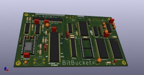
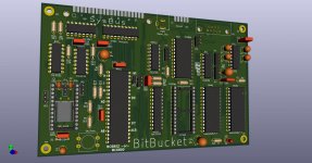
My BitBucket rebuild is coming along slowly, but nicely...
It is a standard Eurocard size. 160x100 mm

BB.jpg

Hopefully not too many design errors, I hate trowing away PCB´s.

To be continued....

Jos
 
I always thought pin 35 (for a 6802) should be a supply voltage? Could I suggest wiring pin 35 to the middle pin of a 3x1 header with the other two pins connected to +5V and 0V respectively. This would allow pin 35 to be not connected, jumpered to +5V or a little plug used to supply an external battery (if required). The addition of the two power supply rails would permit a rechargeable battery. As an alternative, you could wire pin 35 to your expansion connector.

Why is JP4 and A13 linkable on SRAM2?

Why the unused RS232 receiver? I would use it for /CTS?

Isn't CS2 on the SIO active low? I think this is just a naming convention as opposed to a logical error.

I think that was it. Excellent work :)!

Dave
 
Hi Dave,

thanks for your input! Please meet JP7 at pin 35 of the CPU !

BB.jpg

JP4 / A13 is there to enable the use of a 6264 SRAM. I have loads of those...
I already put CTS on the spare receiver, and yes the Kicad symbol for the 6850 is wrong / misleading.

The PCB edge extension contacts should allow to connect multiple boards together with a 40pin flatcable.
I intend to make a 6800D2 workalike 7segment / keyboard PCB, and a Lilith interface board.
Depending on usage I might also make a floppy controller PCB, and a battery / powersupply board with 18650 cells.

Jos
 
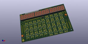
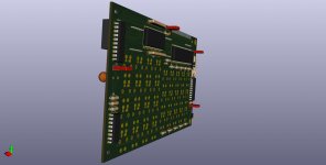
And the second board : display / keyboard also on Eurocard size ( 160x100 mm)

Can be build as a MEK6800D2 functional copy. However I added extra keys & display.
As Dave mentioned in one of the other threads : what do you do with your system once it is build and you have played with it ?

In my case I intend to port the nonpareil HP25 calculator / emulator to the system, and the Bitbucket will then turn into a desktop variant of the Hp25 and earn it´s living that way.

The board ...

BBdisp1.jpg

...with components on the backside...

BB_disp2.jpg


Boards are interconnected with a short 40pin flatcable.


Jos
 
Last edited:
Back
Top