• Please review our updated Terms and Rules here

Terminal CRT Flyback Transformer Question

aplmak

Experienced Member
Joined
Feb 13, 2012
Messages
132
Location
United States
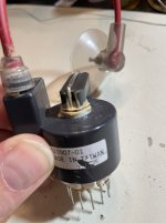
Hey there everyone. Wondering if anyone can help me out. My old flyback transformer on a Wyse type terminal.. similar to 50 I would think (It's actually Altos) but they made them for Altos. At any rate the old one the rod on it was snapped.. so it has to be replaced.

I have looked and looked as I know cross reference part numbers do vary from one manufacturer to another. I am getting one today that is P/N 420017-01 REV. B but I see a lot of replacements with P/N 420007-1 listed... My question is this number imperitive.. it appears to be just a manufacturers part number. The second significant number on the unit which are the SAME on both flyback transformers is: E70954 and they are again the same on both. The only numbers that are different is what seems to be the manufacturers part number. The one part 420017-01 looks exactly like the old one except the lead to the wire clip comes out the front of the side.. the other part comes out of the top.. it really doens't make a difference where it is mounted for that. But there is a white wire going from one of the poles to the encapsulated side area exactly the same as the other.

In a nut shell they appear EXACTLY the same.. and the original and the one I am getting today have the same underwriter symbol I think backwards "R" and then "U" and E70954 the only difference is the "07" and "17" ending in the part numbers.....

Any ideas or suggestions???

Most graciously,
Matt
 
I am not sure why above some of my text has lines drawn through it..... strange... perhaps I am limited on characters? But I did not strike those lines out.... ????
 
The first thing that I'd check when looking at the flyback is the pin-out of the various windings. If it's the same and the resistances are similar, you're probably not in any danger of toasting things.
 
The biggest current supplier of LOPT's is Dalbani Corp. They are on ebay and have a master list of Line Output Transformers, LOPT(flyback) part numbers, plus their equivalents, you might get lucky there.

Otherwise the pin-outs as noted by Chuck(g)

One thing about LOPTs for transistor VDU's, they have very low winding DC resistances on the whole on the primary and most secondaries, often less than an Ohm, except the EHT overwind which cannot be measured easily because, often, the EHT rectifier is integral with the overwind & insulation, but not always.

The winding inductances are important. These can be measured. The turn's ratios can be calculated from the square root of the inductance ratios (because the inductance is proportional to the turns^2). The absolute turns numbers can be calculated by placing a test winding of some turns around the core and applying a diagnostic voltage. I have explained how to do these things in this article, from page 26 on, it applies to all VDU's & TV LOPTs. Suggestions about using non-standard replacement LOPTs are on page 40:

http://www.worldphaco.com/uploads/RESTORING THE PET COMPUTER 9.pdf

If the ferrite core is snapped you can glue it back together with 24 hr epoxy resin and pressure to minimize the gap between the pieces.
 
Last edited:
Well I installed a same part number today and nothing blew up!!! It works!!! I’m leaving it on for a while to burn in the new caps and the new flyback.. the screen dims off which is great so I don’t receive and screen burn. I can assume if it seems to be working well and there is no arc’ing or no buzzing things are good?? I did apply some new silicone grease around the flyback cap rubber and the crt itself for a nice seal.

The broken part on the other one was not the ferrite it was the metal screw that makes a “U” from the back and through the core.. I tried soldering and that didn’t work.. I just assume replace it new.. instead of a hack job. Especially since it has all new capacitors now…
 
I received this one in the mail but the sealant broke.. what the heck kind of epoxy or sealant is this???? I didn’t end up using this one..
 

Attachments

  • AA581DDE-AD2F-40FD-9149-4143BABA41BB.jpeg
    AA581DDE-AD2F-40FD-9149-4143BABA41BB.jpeg
    663.9 KB · Views: 14
It should be fairly easy to fabricate a new "U" shaped retention bolt from standard rod stock. Just run a tap over the ends and Bob's your uncle--or should be...
 
I received this one in the mail but the sealant broke.. what the heck kind of epoxy or sealant is this???? I didn’t end up using this one..
This transformer has an identical physical configuration to the one in the Apple Mac VDU. But its windings may or may not be different.

Don't worry about that cracked glue, the transformer will still be ok.
 
Ok awesome! Well the one I used that is supposed to be the correct one eventually seemed to burst a cap. It’s a 4.7uf 50v BP cap. But the cap is extremely small compared to the original.. didn’t seem right! Now in another terminal I used a Nichicon from 2009 that was the same size and it has marked on it: 4.7uf 50V BP-S and date code H1109

I cannot find a replacement cap like this on Mouser..

So I put in the old 1985 one and I also replaced the Flyback Transformer with the correct one that has that crack in the glue as mentioned above. I’m pretty positive it is an exact match! The flyback I had prior was a little larger and before the 4.7 cap blew it was a lot hotter! So I’m not sure if the small 4.7uf 50v BP cap I had that blew was because it’s the wrong type of cap or if it was the wrong flyback transformer.

Any ideas? Sorry Im not proficient with metering out the terminals on the flyback transformer. But I can say I’m almost positive the one with the little cracked glue is the one it needed!!!

Any ideas on that 4.7 bi polar cap problem??? I ordered the only one I could find which is the same one I have in my other good terminal.

Btw the terminal worked but that 4.7 eventually blew. As it stands again I have the right flyback in there and the 1985 4.7 BP cap.

Here are some pics of the cap. The small one is 4.7uf 50v BP and the second one is the one I ordered that is in my working terminal and same size as the original which was 35v btw.. I always kick the voltage up. So I brought it to 50v. The original only calls for 35v
 

Attachments

  • B360A2A7-03A3-40E5-A925-AA360310636A.jpeg
    B360A2A7-03A3-40E5-A925-AA360310636A.jpeg
    723.9 KB · Views: 2
  • 6BAC791E-893E-4F3D-8F88-23405ACB11F5.jpeg
    6BAC791E-893E-4F3D-8F88-23405ACB11F5.jpeg
    83.3 KB · Views: 2
Given that these caps probably function at 15-18Khz, I'd probably go with a film/polyester cap, not an electrolytic. They're inherently bipolar with a practical ESR of 0.
 
You cannot use a bipolar electrolytic cap to replace the non-polar yoke coupling capacitor in a VDU.

The original capacitors were either film types or oil filled and had an ESR an order of magnitude lower than any bipolar electrolytic cap. Typically the ESR of the originals is in the order of 0.1 Ohms or less. If you put the bipolar electrolytic in there, the H scan linearity will be poor and the capacitor will heat up and out-gas.

As Chuck says, you need to replace it with a film capacitor, anything above 63V rated is fine. The higher voltage range ones, are physically bigger (say a 250V specimen) and work very well for the task.
 
....a capacitor like this would be fine and likely a similar size to the original part:


Of if that one was too physically large you could go to:


Generally though the high voltage units are more robust and have the lower ESR (unlike electrolytics, where the ESR increases with the voltage rating) Generally if you measured the ESR of a 4.7uF MKT film capacitor it would fall in the range of 0.1 to 0.2 Ohms, depending on the type of ESR meter. (A 4.7uF bipolar electrolytic is hopeless for the task and the ESR would likely be over 1 Ohm, unsuted to the task because the peak H yoke coil current in your VDU is higher than you might expect, in the range of 2 to 3 Amps)
 
Last edited:
Those should work--it's not unusual to find "orange drop" capacitors in this application. The rule of thumb is that electrolytic capacitors are terrible at higher frequencies. That's why a very common repair is replacing them in switching power supplies, for example--the high ESR results in slowly cooking them.

The other aspect is the change in bipolar electrolytic chemistry over the years. The motor start/run capacitors used in my home's heat pump get replaced every five years or so as they slowly dry out. Manufacturers have been struggling since the PCB ban in the early 1980s--this has been a problem for electrical utilities who use banks of the things for power factor correction (PFC). An old GE Pyranol capacitor could have a practical working life of 30 or 40 years; not so with modern electrolytics.

In the last decade or so, film capacitors suitable for this application have started becoming used more. The penalty is higher cost and larger size, but much longer life.
 
Would this do perhaps?? I have it on hand…

Trust me if I can avoid electrolytics I do!!! I hate them but sometimes you have no choice.. for regular motherboards the smaller sized I use tantalum where I can all the time.
 

Attachments

  • image.jpg
    image.jpg
    1.6 MB · Views: 6
Looks okay, worth a try.

I hate to break it to you, but tantalums are electrolytic, though they use a dry manganese dioxide electrolyte and so have less chance of drying out. But they're still polar (anode and cathode) and so qualify as electrolytic--they'll often fail spectacularly if the applied polarity is reversed. Their failure mode is usually caused by a phenomenon called "field crystallization" where the tantalum pentoxide breaks down chemically, leading to higher leakage current and heating and tends to be runaway.

A film capacitor is just two conductive elements separated by an insulating film, and so are inherently nonpolar devices. Their failure modes are quite different--moisture can intrude or overvoltage can cause punch-through of the insulating film--or the insulating film can break down chemically over time. Most manufacturers spec a working life of 100K hours or more.
 
Last edited:
Wow I thought tantalums were solid state. At any rate I use them mostly on Mac logic boards because the electrolytic tend to cause horrible damage when they leak. Trust me I’ve seen a reverse polarity tantalum explosion lol…

Thanks!
 
Back
Top