• Please review our updated Terms and Rules here

The Dead Kaypros Society

durgadas311

Veteran Member
Joined
Mar 13, 2011
Messages
1,774
Location
Minnesota
Something that seems missing for the many Kaypro computers that show up in a marginally-working state is the ability to do some debugging when you can't boot and reliably run CP/M. To that end, I've been working on a monitor ROM that one could use to replace the boot ROM in a Kaypro, then connect a terminal (or, better, a terminal program on a PC), and then peek and poke around the system to see what is working and what is not. This is currently being used to diagnose a Kaypro where the CRT won't start up, and I am also getting ready to use it to diagnose my own 2X where I start getting bad sector errors after it's been powered-on a few minutes (which makes CP/M unusable).

The monitor provides your basic debug commands for examining and altering memory and I/O, and the basic ability to poke some instructions into memory and execute them. It also has a small set of specialized test/debug commands that are focused on the core hardware necessary to boot and run CP/M: keyboard, CRT (for models with the 6545 CRT chip), and floppy subsystem. The monitor is intended to run on any Kaypro model, although the early Kaypro-IIs have a particularly limited ROM size (2716 only), and so I make a strip-down version that fits in 2K.

It still needs some commands for the Kaypro 10 harddisk, but I'd like to hear from folks that have had to diagnose WD1002 issues to see if there are things that would help in that area.

I've also made a ROM image that is nothing more than a memory test, for cases where you can't even run the monitor (and suspect bad RAM).

This is still a work in progress, so input would be appreciated - what do YOU need in a case like this? Also, anyone that would like to use this feel free, and keep in touch and let me know how it goes.

Current document is kept here: http://sebhc.durgadas.com/kaypro/monitor.pdf. The ROM images are in the same folder.
 
That sounds like a really cool idea - especially as I hope to get a Kaypro in the future, have no knowledge of them or a working one for comparison, and am very likely to end up with a dead one.

Looking forward to hearing how it goes.
 
Hi Durgadas,

I could have used something like this a while back when I was patching the Advent Turborom to use an older ACEC hard disk controller. Detailed here: kaypro-4-with-a-mini-winnie
I skimmed through your document above, and the one thing that came to mind is that most of the time you would be dealing with the low level format failures....i.e. dead sectors that cause the system to fail. What I think would be needed are some simple looping constructs or macro constructs that allow for executing a command repeatedly while incrementing registers based on a disk geometry that can also be set. I also think that it would be nice to be able to set the base register value so that alternative controllers with WD1002 (like the ACEC) could be managed. Many old Kaypros had alternative hard drives installed (and ROM) that had more capacity and different geometry from the 306 cylinders and 4 heads, Think Seagate ST-225 at 615, 4.. I think the macros would need to work with read commands and seek commands so that you could test the electronics behind seeking and then the ability to read data. There would be bonus points to be able to construct a buffer to use with the format command so you could selectively format tracks in an attempt to recover data.

Chris V.
 
Yes, I've been thinking about how to add a command to do a FORMAT TRACK. It is a bit risky, though, as one could trash an HDD unintentionally. Probably need to work out some safety measures. I also don't have a K10, so can't test on real hardware - although I probably wouldn't want to trash my HDD just to test it out.

I'm not sure how far to go with HDD diagnosis, too. Media failure really forces one to decide whether to try and recover or just reformat and start over. either way, the solution is probably to boot a floppy and go from there. I am trying to keep the ROM within 8K, so that it will work on Kaypro IV and 10 models, that can only take a 2732.
 
I wish I knew how to add a HD to my 2x. Don't know if it just requires the adding of many chips, some resistors, and caps or something more. And of course a different ROM.
 
The HDD interface uses a relatively small number of chips that are still available, I think. I also believe that the 2X mainboard will work with the 81-478 ROM, so that it will auto-detect your configuration. You do have to, however, get rid of the second floppy drive. The thing you can't get easily is the WD1002-05, but I believe you can use the Kaypro FreHD instead, to at least emulate the controller.
 
I added a HEX download command to the monitor, so that more-complex programs can be run. This should help with custom needs, but still requires someone write the code initially.
 
Yes, I've been thinking about how to add a command to do a FORMAT TRACK. It is a bit risky, though, as one could trash an HDD unintentionally. Probably need to work out some safety measures. I also don't have a K10, so can't test on real hardware - although I probably wouldn't want to trash my HDD just to test it out.

I'm not sure how far to go with HDD diagnosis, too. Media failure really forces one to decide whether to try and recover or just reformat and start over. either way, the solution is probably to boot a floppy and go from there. I am trying to keep the ROM within 8K, so that it will work on Kaypro IV and 10 models, that can only take a 2732.
I think if someone has the knowledge to program and put a new ROM in, we can assume that they would understand more about the system. I would put the format command underneath two layers of Are you sure? Then again, if macros could be created, I would want the ability to scrap the warnings for myself.

BTW, it would be interesting to be able to load data and programs with the hex load feature. Maybe it does already?

BTW, in most of my dealings with KayPro, the screen memory and main memory chips have been the culprit most of the time. Followed by bad display boards and power supplies because of bad capacitors. Sometimes even reseating all of the chips will help immensely. In your CRT testing, potentially see if you can test screen memory? Then, an exhaustive test on main memory that points to a chip. Again, when I'm debugging a dead KayPro, I usually start with basics: Is there voltage? Is the filament in the CRT glowing? Are they XY filter caps looking like they will blow at any second? If I get beyond that, I'll replace all of the main memory 4164's. If screen corruption is taking place, I'll change the 2K screen memories (I forget the part# off the top of my head) I have a pile of old kaypro boards to pull parts from though. That helps.

Chris V.
 
...
BTW, it would be interesting to be able to load data and programs with the hex load feature. Maybe it does already?
...
Chris V.
Yup, just added HEX load today. That should help with a lot of the debug. Could even write some memory tests.
 
Here are the results of Douglas helping me troubleshoot a Kaypro 4/84 Motherboard with
a problem booting from Floppy.


I'm working on a Kaypro 4/84 that has a Motherboard 81-184, with ROM 81-292A.
I have Verified the ROM has good Code. On Power up the Motherboard is starting
the Boot process as the LED comes on for Drive A: and it moves the head to
track 0. After the computer steps Floppy A: to track 0, the Keyboard LED comes "ON",
and nothing happens after that.

I've checked the Crystal Frequency, and the Frequencies generated from the
U10 Gate Array (CCLK) for U10 81-189. I've verified the Crystal frequency on
Gate Array U23 and the 4800 HZ, 1 MHz, 2 MHz, and 4 MHz generated from U23 81-194.

I've verified the following signals back to the FDC Pins, and all are good and
working correctly. Note that the Floppy Must be SELECTED to get the INPUT signals
to the FDC.

1. FDC Pin 35 = INDEX Pulse from Floppy Drive
2. FDC Pin 34 = Track 0 Sensor from Floppy Drive
3. FDC Pin 36 = Write Protect from Floppy Drive

I moved my Floppy Drive's Head to the inner track, and on Power up, it steps
to the outer track. So, stepper Motor, and logic are working for stepping.
The Motor also runs to spin the floppy media. But, it's not reading my boot
floppy.

I've verified the FDC Pins 26 and 27.
FDC 9216 Pin 7 is FDATA to FDC Pin 27.
FDC 9216 Pin 2 is FClock to FDC Pin 26

I've even changed one Memory IC, and replaced D0 thru D7 moving the New RAM IC
in each D{0..7} position. No Change in operation of the Motherboard.


I'm trying to test the FDC to get it working on that problematic Motherboard.
I've installed Monitor 2.7, and moved the head to track 39 with power OFF.
When I power up, the FDC steps the head to track 0.


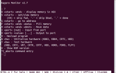
The Kaypro Monitor's commands are:
Code:
  Kaypro Monitor v2.7
  : ?(CR)
  D <start> <end> - display memory in HEX
  S <start> - set/view memory
      (CR) = skip fwd, '-' = skip bkwd, '.' = done
  G <start> - go to address
  F <start> <end> <data> - fill memory
  M <start> <end> <dest> - Move data
  I <port> [num] - Input from port
  O <port> <value> [...] - Output to port
  H - Hexload program
  N <hw> - iNitialize hardware (KB83, KB84, CRTC, HDD)
  T <hw> - Test hardware
    (KBD, CRTC, VRT, CRTR, CRTF, HDD, HDRD, FDRD, FLPY)
  V - Show ROM version
  ^C aborts command entry
    .
    .

The Kaypro 4/84's Ports are as follows: (Modified to be correct for the 4/84
Motherboard from the Version F Manual.)
Code:
               Port#
     Use     (hex)      Device         Function
     System:
             14 - 17    74 373         System output port.

                                       Bit functions.
                                       0 0=Select floppy A (C on K10).
                                       1 0=Select floppy B (Hard disk on K10).
                                       2 0=Select side 1, 1=Select side 0.
                                       3 0=PSTROB.
                                       4 1=Floppy motor on (48 tpi drives).

                                         (FOR HIGH SPEED, HIGH Density Drives)
                                       4 0=Floppy motor on (48 tpi drives).
                                          1=Select high speed (High density drive). * see note below.

                                       5 0=Select double-density.
                                       6 0=Select normal character set.
                                       7 0=Select 64K RAM.
                                         1=Select ROM (RAM 8000-FFFF).
                     
                        74 244         System input port.
                  
                                       Bit functions.
                                       0 0=floppy A selected (C on K10).
                                       1 0=floppy B selected (Hard disk on K10).
                                       2 0=Side 1 selected, 1=Select side 0.
                                       3 0=PSTROB.
                                       4 1=Motor is on (48 tpi floppy).
                   
                                         (FOR HIGH SPEED, HIGH Density Drives)
                                       4 0=Floppy motor on (48 tpi drives).
                                          1=Select high speed (High density drive). * see note below.
                                                            
                                       5 0=Double-density is selected.
                                       6 0=Parallel printer is busy.
                                       7 0=64K RAM is selected.
                                          1=ROM (RAM 8000-FFFF) selected.
 
   * Note on high-density drives:

   A 1 in bit position 4 will select high speed on the high-density diskette
   drive.  To reset the drive to low speed it is necessary to change this bit to a
   0 AND open the drive door, then close it.

I've read port 0x14, and I get a response of 0xE7.
I 14
INPUT 14 = 0xE7 = 1110 0111 Binary.

I used the floppy stepping rate of 30ms since I know the Kaypro's Tandon Floppy
Drives require a step rate of 30ms.
Code:
    r1 r0 Stepping rate
    0  0  6 ms
    0  1  12 ms
    1  0  20 ms
    1  1  30 ms     <-------------b1 & b0

The Type I commands will use this stepping rate.

Now, I need to calculate my command for a SEEK to track 20 = 0x14
The SEEK Command is 0x13 (for 30ms stepping rate) and the Data Register 0x17 is
loaded with the Desired Track.

O 17 14
T FLPY 13

But, that doesn't make it step.


Code:
Command Summary (models 1791, 1792, 1793, 1794)

    Type    Command            b7 b6 b5 b4 b3 b2 b1 b0
    I    Restore               0  0  0  0  h  V  r1 r0
    I    Seek                  0  0  0  1  h  V  r1 r0
    I    Step                  0  0  1  T  h  V  r1 r0
    I    Step-In               0  1  0  T  h  V  r1 r0
    I    Step-Out              0  1  1  T  h  V  r1 r0
-------------------------------------------------------------------
    II   Read Sector           1  0  0  m  S  E  C  0
    II   Write Sector          1  0  1  m  S  E  C  a0
    III  Read Address          1  1  0  0  0  E  0  0
    III  Read Track            1  1  1  0  0  E  0  0
    III  Write Track           1  1  1  1  0  E  0  0
    IV   Force Interrupt       1  1  0  1  i3 i2 i1 i0

A simple program to /WR (and /CE) to the WD1793 would be:

: S8000
8000 00 AF
8001 00 D3
8002 00 13
8003 00 C3
8004 00 01
8005 00 80
8006 00 .
: G8000
GO 8000 ?Y


Continuously stepping in/out is more complicated, but you can issue single STEP IN and STEP OUT
commands to the WD1793 manually:

: T FLPY 53
41 0000
40 0001

: T FLPY 73
41 0000
40 0001

:

Command 53 is STEP IN (away from track 0), and 73 is STEP OUT (towards track 0). Each performs a
single STEP, with direction set according to the command.


I've calculated my byte should be 0x96 to turn on Motor for A:, Double Density, Side 0.

That works fine.


I checked the CLOCK on Pin 24 and I get a 1 MHz Square wave clock signal.


When I use O 17 14 <CR>
and T FLPY 13

I get a response but no head movement. I know my floppy drive
works with another motherboard.

I used your example code to send the Write (/WE) signal to U44 FDC 1793.
I did not have the /WE Signal on Pin 2 of the FDC U44 1793. I chased that
back to Pin 8 of U52 74LS32. On U52 Pin 9 was working correctly but Pin 10
was stuck at about 1.8 volts.

See U52-Pin10.jpg

I had a spare 74LS32 and replaced it. Now, I had the /WE Signal at Pin 2 of
FDC U44 1793.

Next, I tried stepping the head towards the center of the floppy (Track 20 = 0x14)
and that worked. I then restored the head to track 0 and read the Boot Sector
into 0x8000 to 0x8100. That worked fine. So, I replaced your Monitor ROM
with the OEM ROM, and Booted the Kaypro with the Video Board connector
unplugged. The Motherboard booted to CP/M, and when I did a DIR<CR>
I got a read from Drive A:.

Another Kaypro fixed with Douglas's Monitor.

Larry
 

Attachments

  • diags-061023.pdf
    148.5 KB · Views: 6
  • monitor-061123.pdf
    158.2 KB · Views: 4
  • U52-Pin 10.jpg
    U52-Pin 10.jpg
    2.9 MB · Views: 3
  • WD-1793.txt
    22.4 KB · Views: 4
Last edited:
Hi guys,

I took my time again to my two
Play Kaypros 4/84.

1. Kaypro 4/84 now also has Mean Well RT-85B power supply.

2.Kaypro 4/84 mud durgadas311
monitor.bin tested.
Works as described by durgadas311.
Very good work.

Now I would like to write a small test program.
As I see it, the RAM area can be used from 8000H.
From 0000h RAM should also be possible.

The transmission of a HEX file with minicom (ascii ctrl a+s) should work?

I'll try it.

Thanks for the great work.

greeting
Kurt
 

Attachments

  • Bildschirmfoto vom 2023-07-14 22-36-05.png
    Bildschirmfoto vom 2023-07-14 22-36-05.png
    87.2 KB · Views: 8
Let me know if you have any problems, but you should be able to load a HEX file. Make certain it is ORGed at 8000H or above (but below F000H).
 
Hi
call 013h outputs str.
It works with H montest.hex
G8000


greeting
Kurt

please change montest.txt.
 

Attachments

  • montest.txt
    384 bytes · Views: 4
Last edited:
Hi
call 09ffh outputs str.
It works with Hmontest.hex
G8000


greeting
Kurt
Please note, do NOT call 09FFH as that is an internal routine and that location will change over time (in fact, the latest version of the ROM has something else entirely at location 09FFH). The official entry point for the print string routine is 0013H. See section "Running Programs" in http://sebhc.durgadas.com/kaypro/monitor.pdf for the official entry points that are available.

Also note that it is not normally required to switch stacks. As long as you don't overwrite the monitor stack (top of memory, 0FFFFH downward), you can just leave SP as-is and RET when finished.
 
The monitor ROM provides some entry points to utility functions that programs may use.
Yes Perfect.

Does floppy disk access work with Gotek LW.
I haven't been able to access it yet.
 
Does floppy disk access work with Gotek LW.
I haven't been able to access it yet.
I'm not sure, I only have the original Epson floppies. I believe the GoTek should be "pretending" to be a floppy drive with floppy diskette inserted (when an image file selected), so the Kaypro's WD1793 should be behaving as expected. As far as the Kaypro (and monitor ROM) is concerned, it's just a floppy drive and floppy diskette.
 
When using 28C64 or 27C64 in the Kaypro 484
I find the connection after durgadas311 description
via NC, WE, VCC to RDC and A12.
PIN 26,27,28 -->1,2.

Why A12. I'm not connected to A12 and it's been working fine for a number of years.

Could it be that the PIN otherwise remains open and can cause problems?

Thanks for an info.

Kurt
 
Doesn't your 4/84 have a 28-pin socket on the mainboard? In that case, you just insert the 28C64 without any special connections. If you had an older mainboard (K10 or */83) with a 24-pin socket, then you'd need the adapter and connections for pins 26,27,28,1,2.
 
Back
Top