Crashedfiesta
Experienced Member
- Joined
- Apr 16, 2022
- Messages
- 85
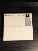
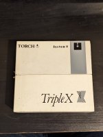
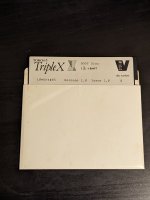
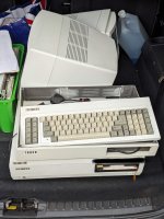
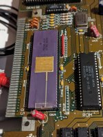
My work colleague has been at it again and given me a Torch Triple X computer with various other bits and pieces including schematics, manuals, loads of disks and cables. I've been very cautious about just whacking power into it (good job too) and I've learnt a lot about floppy disks and the Greaseweazle, having managed to back up the majority of the Unix System V floppies that come with it (the last three - of 18 - need more attention and might be gone forever but are only 'man' pages so I hope not too important).
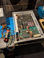
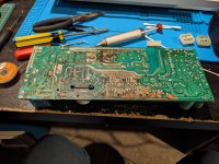
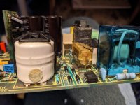
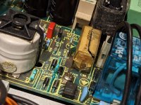
So, the power supply was a 1980's special in that it had a 'soft touch' to turn on and off. To achieve this is had a battery inside. Yep. You can see where this is going. The battery has effectively destroyed the power supply. I tried to repair it but, not being an expert on PSUs my attempts were a failure. I suspect it is too far gone (see pictures).
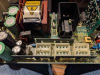
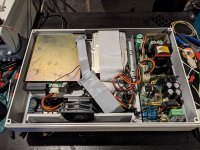
The main boards inside the machine are unaffected by the battery leakage so I rigged up an old ATX power supply to power the computer up. It's missing the -5v but this is only needed on the serial port and, apparently, to drive the speaker beep. At the first switch on there was no sign of life at all. The 12v rail is fine but the 5v rail is down at less than a quarter of a volt. This says to me that there is a short on the board. I had thought that the thing may be waiting for a 'soft start' signal but looking through the manuals it looks like that signal is all generated in the PSU and is only concerned with starting the 5v supply to the board. Once it's started the board itself generates a signal back to the power supply to keep it on. By this logic, feeding 5v directly into the board should just trigger the startup procedure. But it doesn't.
Has anyone else had any experience with these machines? They seem to be so rare that I really don't want to make a mess of it...
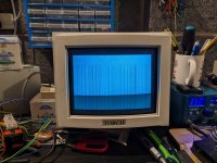
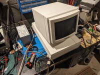
I have confirmed that the floppy drive works OK as I've been using it with the Greaseweazle. The hard disk has not been switched on yet but I might feed power directly into it just to see if it will work.
So, the power supply was a 1980's special in that it had a 'soft touch' to turn on and off. To achieve this is had a battery inside. Yep. You can see where this is going. The battery has effectively destroyed the power supply. I tried to repair it but, not being an expert on PSUs my attempts were a failure. I suspect it is too far gone (see pictures).
The main boards inside the machine are unaffected by the battery leakage so I rigged up an old ATX power supply to power the computer up. It's missing the -5v but this is only needed on the serial port and, apparently, to drive the speaker beep. At the first switch on there was no sign of life at all. The 12v rail is fine but the 5v rail is down at less than a quarter of a volt. This says to me that there is a short on the board. I had thought that the thing may be waiting for a 'soft start' signal but looking through the manuals it looks like that signal is all generated in the PSU and is only concerned with starting the 5v supply to the board. Once it's started the board itself generates a signal back to the power supply to keep it on. By this logic, feeding 5v directly into the board should just trigger the startup procedure. But it doesn't.
Has anyone else had any experience with these machines? They seem to be so rare that I really don't want to make a mess of it...
I have confirmed that the floppy drive works OK as I've been using it with the Greaseweazle. The hard disk has not been switched on yet but I might feed power directly into it just to see if it will work.
Attachments
-
 markup_1000004313.jpg642 KB · Views: 32
 -
 PXL_20230924_202437471.jpg2.3 MB · Views: 35
 -
 PXL_20230924_194519547.jpg1.1 MB · Views: 35
 -
 PXL_20230907_210616772.jpg1.3 MB · Views: 30
 -
 PXL_20230907_180023695.jpg595.2 KB · Views: 30
 -
 PXL_20230907_180005572.jpg775.9 KB · Views: 29
 -
 PXL_20230907_180000884-EDIT.jpg2.3 MB · Views: 28
 -
 PXL_20230907_174748667.jpg751.4 KB · Views: 27
 -
 PXL_20230907_174738141.jpg1.9 MB · Views: 26
 -
 PXL_20230907_174545435.jpg1,010.2 KB · Views: 28

")
 )..
)..