• Please review our updated Terms and Rules here

Toshiba T1000SE damaged component

Papalapa

Member
Joined
Mar 5, 2024
Messages
13
I'm trying to repair a Toshiba T1000SE laptop computer. When connected to the mains, the DC IN light turns on but nothing else. This kind of laptops do not turns on if the battery is not set and as I don't have a good battery I apply the 7,2 volts directly to the battery terminals from an AC adapter. No success.

After opening the laptop I have seen that most of the electrolitic capacitors in the power supply area were damaged and leaking:
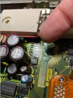
capacitor.jpg

I unsoldered the capacitors and carefully cleaned the PCB and now are ready to receive the new capacitors, but I also found a resistor labeled R501 in the PCB that I cannot identify. It's in the power supply area and it's burnt. I drawn a red rectangle in the picture where the R501 is soldered:
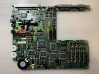
IMG_3675.jpg

The inscription seems to be "7J 90 1W". Maybe a 90 Ohms 1Watt resistor ?

IMG_3674.JPG

I have the Service Manual of this computer but there's not any schematic inside. Someons has or knows where the schematics cam be found ? I Iooked everywhere unsuccesfully.

Many thanks!
 
You must be member papalapa at [here].

I wonder if your R501 was blue, like the one pictured in post #1 of the thread at [here].

I think it likely that R501 was damaged by something else on the board. Obviously, the circuit diagram will help (compared to working it out visually and via multimeter) in that regard, but if I was aware of any circuit diagram, I would have added it to [here].
 
It's unlikely that you could have such extensive damage that didn't include some of the semiconductors as well as the caps and resistor. You're right to look for schematics, because without it will be extremely hard to repair. Even with schematics it might not be worth the time, but only you can make that judgement. Good luck!
 
A tip,
Isolate the supply from the board by desoldering the set of jumpers. See if you can get any life before the controller shuts it down.

Also,
After I replaced the caps, I had to track down fried semiconductors on the board. I had a dead rs232 buffer, a dead switch mode controller, one or two small smt transistors and a diode or two.

I scavenged parts from a dead Toshiba 486 laptop.

The controller is in the top left corner. It enables a set of PWM controllers that regulate the rails. If the rails don't come up, the controller shuts it all down. The PWMs are up beside the controller.

When the caps die, I think there are some failure modes that burn up some parts. It is hard to say because sometimes the act of repairing can cause more breakage since we have incomplete info.

Anyhow, it could take some effort to debug. In the end I had to make some compromises. If I kept trying to make it perfect I was eventually going to kill it. So I disconnected the 12v feed and separately added a regulator to simulate a 7.2V battery. So I can only run off external power but that's OK.

I'm happy to share what I did if it helps.

Best of luck.
 
Last edited:
You must be member papalapa at [here].

I wonder if your R501 was blue, like the one pictured in post #1 of the thread at [here].

I think it likely that R501 was damaged by something else on the board. Obviously, the circuit diagram will help (compared to working it out visually and via multimeter) in that regard, but if I was aware of any circuit diagram, I would have added it to [here].

Yes, I am the same "Papalapa", I use to visit several retro-computer forums and that's one of them.

As you can see in my picture I don't know if R501 was blue or not because it burnt, but anyway, as is the same computer model it should be the same component. I have seen this post and also a video in youtube but I'm not able to read the resistor value unfortunatelly.

As you say, most probably R501 was damaged due to the electrolitic capacitors of the power supply area. They were seriously damaged and with liquid leaks,
 
A tip,
Isolate the supply from the board by desoldering the set of jumpers. See if you can get any life before the controller shuts it down.

Also,
After I replaced the caps, I had to track down fried semiconductors on the board. I had a dead rs232 buffer, a dead switch mode controller, one or two small smt transistors and a diode or two.

I scavenged parts from a dead Toshiba 486 laptop.

The controller is in the top left corner. It enables a set of PWM controllers that regulate the rails. If the rails don't come up, the controller shuts it all down. The PWMs are up beside the controller.

When the caps die, I think there are some failure modes that burn up some parts. It is hard to say because sometimes the act of repairing can cause more breakage since we have incomplete info.

Anyhow, it could take some effort to debug. In the end I had to make some compromises. If I kept trying to make it perfect I was eventually going to kill it. So I disconnected the 12v feed and separately added a regulator to simulate a 7.2V battery. So I can only run off external power but that's OK.

I'm happy to share what I did if it helps.

Best of luck.
Many thanks for your tips and information. The picture of the T1000xe PSU helped me a lot. In case of that I'll not be able to repair the PSU maybe I can use an external PSU ti inject the +5v, +12v and and -9v. We will see...
 
Back
Top