• Please review our updated Terms and Rules here

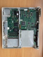
Toshiba T1200XE restoration post

It's very difficult to figure this out, because there is no clarification anywhere in the manual, to tell what each acronym means, because there is ambiguity in what it could stand for.

Normally, IBM 5150 and systems that used this standard had a pin that would specify stable power, and allow the motherboard to turn itself on. If 5 volts is not present on this pin, it would not activate.

Try connecting 5 volts to this pin. you may be able to get something from it. This is just a guess, though. Be careful, and DO IT AT YOUR OWN RISK:
Pin 37: PCLR (POWER CLEAR? Meaning "Electrical power is stable"?)
 
Try connecting 5 volts to this pin. you may be able to get something from it. This is just a guess, though. Be careful, and DO IT AT YOUR OWN RISK:
Pin 37: PCLR (POWER CLEAR? Meaning "Electrical power is stable"?)
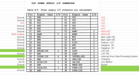
I will try this.

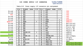
Below, in my opinion, is how the pins are defined.
There are also several definitions that are missing that I am unable to decipher.
I've connected 5V to the red-marked pins.
20230321111619.png
 
Last edited:
It's very difficult to figure this out, because there is no clarification anywhere in the manual, to tell what each acronym means, because there is ambiguity in what it could stand for.

Normally, IBM 5150 and systems that used this standard had a pin that would specify stable power, and allow the motherboard to turn itself on. If 5 volts is not present on this pin, it would not activate.

Try connecting 5 volts to this pin. you may be able to get something from it. This is just a guess, though. Be careful, and DO IT AT YOUR OWN RISK:
Pin 37: PCLR (POWER CLEAR? Meaning "Electrical power is stable"?)
Unfortunately, nothing has changed :(
Any other good suggestions ?
 
All right, try ACIN or PSRD (This could mean Power Supply ReaDy).
According to the manual, the PSRD pin is OUT.
Does this mean that the signal is comes out of mainboard to the PSU?

I will try the ACIN.
 
Hello, I am following this post closely, I have a T1200XE with (you guessed it) toast PSU.
I was thinking of repurposing the modern PSU circuit made for the T1200 (link) for the T1200XE PSU board form factor once we get a working system.
 
Hello, I am following this post closely, I have a T1200XE with (you guessed it) toast PSU.
I was thinking of repurposing the modern PSU circuit made for the T1200 (link) for the T1200XE PSU board form factor once we get a working system.
I'm a novice. My knowledge of electronics was limited. And I'm not an electronics professional. I have a small window of time in the evening to work on my computer. Thus, this post's update progress will be impacted. Due to my recent workload, I had to put this computer's repair on hold for a short while.
In order to determine whether these two computer(T1200&T1200XE) PSU have anything in common, I'm also study on this T1200 PSU project. There is a significant difference between the two—less so than physically.
 
I've connected 5V to the red-marked pins.
Not sure if that was a good idea. The fact that the RAM has extra voltage pins indicates that it may not run at 5V. Maybe at 3.3V instead, so you might have killed some of the RAM chips.

Apart from that, why don't you connect an external display? That would be the easiest way to see if the system does something at all.
 
Not sure if that was a good idea. The fact that the RAM has extra voltage pins indicates that it may not run at 5V. Maybe at 3.3V instead, so you might have killed some of the RAM chips.
Not according to the maintenance manual cited here, if I'm not mistaken:
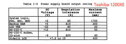
The main power is 5 volts, according to the maintenance manual .(System Logic, FDD, HDC, RAM & HDD)

View attachment 1254262
 
I'm a novice. My knowledge of electronics was limited. And I'm not an electronics professional. I have a small window of time in the evening to work on my computer. Thus, this post's update progress will be impacted. Due to my recent workload, I had to put this computer's repair on hold for a short while.
In order to determine whether these two computer(T1200&T1200XE) PSU have anything in common, I'm also study on this T1200 PSU project. There is a significant difference between the two—less so than physically.
That's a bummer! I hope you will have time soon to continue tinkering.
I am a computer engineer so I have some electronic knowledge plus some prior experience, so I hope that when I will look deeply in the circuit (plus the info from this forum) I won't be overwhelmed 😅.
If you manage to find the bare minimum pins and voltages to supply I will be more than happy to contribute on the PCB side of things.

Question: are you applying voltages with the power supply board powered or not?
 
Not sure if that was a good idea. The fact that the RAM has extra voltage pins indicates that it may not run at 5V. Maybe at 3.3V instead, so you might have killed some of the RAM chips.

Apart from that, why don't you connect an external display? That would be the easiest way to see if the system does something at all.
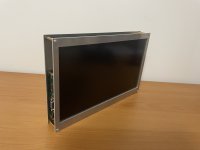
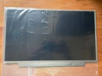
I am working on assembling a VGA monitor using my old laptop LCD, and the driver board is on the way.
20230326110307.jpg

The RAM of that time powered by 5V voltage, according to the manual and the result of memory chip query.

20230326101946.jpg微信截图_20230326102112.png


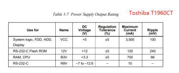
According to the manuals, the PSU on my Toshiba T1960CT has 3.3 voltage unlike the T1200XE.
20230326103551.png20230326104203.png

Toshiba Vantage Notebook Maintenance Manuals (Almost All)
 
Last edited:
The pins of PSU have been Updated.
I still lack the time to perform a power-on test.
20230328154341.png
I'm not certain about the green pins.
 
20230328155741.png
Can anyone tell me what "100,001,000" actually mean?
How to do it electronically?
 
Hi
I have a T1200 with a dead PSU, and have recently been assembling a replacement PSU (custom PCB) for the unit. The project is open source (I am going to write a full post about it, someday); the initial hardware revision, along with a few fixes, can be found here:

I've recently found out that a similar PSU project exists already (linked here above), but since it doesn't fully support all the original features, and I started mine already, I decided to continue my work. My primary focus was to include features like Auto-Resume (that "hibernation" style shutdown - which explains the separate RAMV supply) and battery operation.

Now, I'm not sure how similar (or different) the T1200 is from the XE (the PSU voltages are the same), but feel free to take a look at my schematic, or ask if you need any info that I might know :)

I can confirm that the PSRD and PSSD lines are for Receive and Send data, respectively. On the T1200 this is a 512 baud, 8-bit, MSB-first serial protocol, which has a few commands that enable the battery gauge and Auto-Resume to work. On T1200, the PSU also controls the Reset line (both input and output - i.e. it gets raw signals from the reset button).

One thing you might want to try; if you haven't connected the LCD (or it's broken), chances are that a "System configuration" message is being displayed. This message shows up even before POST and memory test. Pressing Enter on the keyboard clears the message, and a beep can be heard, as well as the FDD trying to boot.


Regards,
Kuba
Thanks!
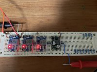
Tomorrow, I'll try to boot it on using four different voltages: 5, 9, 12, and -22.
PCLR(37),BEEP(36),INTDSP(30) I/O pins to the GND, other I/O pins to +5V.
Any suggestions ?
Wish me luck:)

F299D366-4B69-4796-B5AB-727A8B1003C1.jpeg
 
Last edited:
Your voltages are wrong. You should have +5V, +12V, -9V and -22V - note that -9V and -22V are **negative** - I think you only have one negative regulator on the breadboard.
+12V and -9V are not needed for the basic functioning of the system - they're only used for the modem and RS-232 port.

And try to connect the least I/O pins you can. Connecting them blindly to 5V or GND may damage the machine. Try tracing the paths on the PCB to see if a signal goes to a transistor, for example. This way you can predict what voltages are expected on a pin.

Also, always use at least 1K resistors in series on these I/O pins, so that even if you connect something incorrectly, the risk of damage is lower.
 
Last edited:
These days I assembled a VGA monitor using old laptop LCD.
But the T1200XE external display interface is old 9 pins CGA!
It's a waste of time!
B5C70411-140E-4F0F-A602-EEA031ADFD3C.jpeg
 
Your voltages are wrong. You should have +5V, +12V, -9V and -22V - note that -9V and -22V are **negative** - I think you only have one negative regulator on the breadboard.
+12V and -9V are not needed for the basic functioning of the system - they're only used for the modem and RS-232 port.

And try to connect the least I/O pins you can. Connecting them blindly to 5V or GND may damage the machine. Try tracing the paths on the PCB to see if a signal goes to a transistor, for example. This way you can predict what voltages are expected on a pin.

Also, always use at least 1K resistors in series on these I/O pins, so that even if you connect something incorrectly, the risk of damage is lower.
you are right.The voltage there should be -9V.
I have put some 15K resistors on the breadboard inorder to connect I/O pin.
I will take a closer look at the circuit diagram as you suggested.
Thanks a lot!
 
you are right.The voltage there should be -9V.
I have put some 15K resistors on the breadboard inorder to connect I/O pin.
I will take a closer look at the circuit diagram as you suggested.
Thanks a lot!
Hi there! Did you have the time to try out the machine with those voltages?
I'm curious to know how it went!
 
Back
Top