• Please review our updated Terms and Rules here

Toshiba T1200XE restoration post

ohmylove2u

Experienced Member
Joined
Mar 1, 2023
Messages
115
Working on a Toshiba T1200XE at the moment.
Naturally, it doesn't work.
And I believe that restoring it will be a hard work!
微信图片_20230311150211.jpg微信图片_20230311150230.jpg

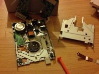
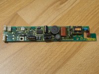
Because caps leak, the system power board and the sidelit power board had suffered serious corrosion.
I removed all caps and cleaned the PCB.
Now I'm just waiting for new caps to arrive.
微信图片_20230311150225.jpg微信图片_20230311150234.jpg

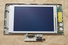
The LCD appears to have a significant issue.
Can anyone tell me if it still works?
微信图片_20230311150221.jpg微信图片_20230311150217.jpg
 
I wish you luck. I started restoring mine years ago and never got it done. It's still here somewhere in pieces... :confused:

Got the screen and the inverter board done, then started with the PSU board. Sadly, that is very hard to solder on and the vias under the leaked caps are mostly toast. Had about 50% done before I lost motivation.

Oh, and the slim-line floppy drive needs a new belt as well - fun. Maybe some day...
 

Attachments

  • P1060951.JPG
    P1060951.JPG
    181.3 KB · Views: 31
  • IMG_20151229_184800_474.jpg
    IMG_20151229_184800_474.jpg
    246.9 KB · Views: 26
  • P1060949.JPG
    P1060949.JPG
    369.5 KB · Views: 26
I wish you luck. I started restoring mine years ago and never got it done. It's still here somewhere in pieces... :confused:

Got the screen and the inverter board done, then started with the PSU board. Sadly, that is very hard to solder on and the vias under the leaked caps are mostly toast. Had about 50% done before I lost motivation.

Oh, and the slim-line floppy drive needs a new belt as well - fun. Maybe some day...
You and I experienced nearly the same issues.
I'm working very hard on it right now.
I wish me luck: (
 
Oh, and the slim-line floppy drive needs a new belt as well - fun. Maybe some day...

You can print belts on a 3D printer using TPU filament. Use the spiral vase setting and endpoint stagger so that each successive line endpoint is moved around the belt to avoid them being in one place. It makes a very strong belt.
 
That’s an interesting idea. How do you measure the original belt dimensions? I’ve got 3 slimline Mitsumi drives that need new ones. Model D359F.

And good luck with that Toshiba, those ELNA caps are the devil. Worst leaking THT caps of the era.
 
Get a piece of string and wrap it around the belt path, then cut it where the ends meet. Measure it and plug it into the circumference of a tube in a 3D modelling program and print that as a spiral vase. It should be pretty close, you'll probably have to make a few prints to get a good fit.
 
You can print belts on a 3D printer using TPU filament. Use the spiral vase setting and endpoint stagger so that each successive line endpoint is moved around the belt to avoid them being in one place. It makes a very strong belt.
One of my methods that has been tested is welding a PU ring.
The key point is to measure the belt's size. when you welding the PU ring, you should cut slightly short material.
But to be honest,I never succesed due to PU lacks elasticity.
 

Attachments

  • 20230314110837.jpg
    20230314110837.jpg
    108 KB · Views: 6
I substituted new caps.
When I plugged the DC in, nothing occurred.
Not even the "DC-IN" Light flashed.
微信图片_20230314135416.jpg微信图片_20230314135421.jpg


Now I don't think i can restorate this machine!
I have 3 choices:
1.Buy a functioning power supply module,but it is too rare.
2.Design a new power supply module. Someone has done this for Toshiba T1200(not XE)
3.Take all circuit out of the body shell include the LCD module, and equip it with Raspberry Pi and new TFT LCD
It's hard to make decisions :(
 
Last edited:
You can print belts on a 3D printer using TPU filament. Use the spiral vase setting and endpoint stagger so that each successive line endpoint is moved around the belt to avoid them being in one place. It makes a very strong belt.
That would be no option for me. My 3d printer can not handle TPU.

Also, getting a replacement belt is not an issue, but the path the belt takes inside the drive means you have to remove the pcb (with fixed flex cables) and the motor - as you can see in the picture. Very easy to break something.

@ohmylove2u did you try giving power over the battery contacts? That's how I tested mine before I started working on it (it was still posting).
 
@ohmylove2u did you try giving power over the battery contacts? That's how I tested mine before I started working on it (it was still posting).
I will try this way tomorrow(Now,it's time to playing with my naughty son:))
 
Last edited:
That would be no option for me. My 3d printer can not handle TPU.

Also, getting a replacement belt is not an issue, but the path the belt takes inside the drive means you have to remove the pcb (with fixed flex cables) and the motor - as you can see in the picture. Very easy to break something.

@ohmylove2u did you try giving power over the battery contacts? That's how I tested mine before I started working on it (it was still posting).
Even with a battery, nothing changed: (
The DC-IN LED just flashs weakly as before.

3F54EC66-DE27-4EC8-A41F-FB1BF0284412.jpeg
View attachment IMG_9114.MOV
 
Last edited:
Too bad. I assume one or more pins of some of the ICs got damaged by the leakage and don't make contact any longer. You probably need to inspect each one under a microscope.
 
That looks like there is a short-circuit somewhere. You may have a bad power regulator (the bright-green, or black, vertical rectangular components), you may have caused a solder connection that is shorting an incorrect power connection, or the leaked chemicals from the capacitors may be causing a shorted connection.

I see what looks like solder flux on a chip in the first picture in this post:
I substituted new caps.
When I plugged the DC in, nothing occurred.
Not even the "DC-IN" Light flashed.
View attachment 1254139View attachment 1254140


Now I don't think i can restorate this machine!
I have 3 choices:
1.Buy a functioning power supply module,but it is too rare.
2.Design a new power supply module. Someone has done this for Toshiba T1200(not XE)
3.Take all circuit out of the body shell include the LCD module, and equip it with Raspberry Pi and new TFT LCD
It's hard to make decisions :(

Cover the entire board with a layer of an automotive oil remover soap (Here in America, we have a few brands of this kind of soap including "Gojo" and " Orange Goop".), but DO NOT USE THE SPECIFIC TYPE OF SOAP THAT CONTAINS PUMICE GRIT. You will scratch the board and possibly damage it. Only get the type that is similar to a gel or is gelatinous.

Use an old toothbrush and some water, and scrub the board, then rinse it with distilled water and let it dry well.

After that, try again.
 
I washed the PSU board with water when all old caps been removed several days ago.
At that moment one little ic fall off.
I had to solder it back.
It's an extremely tough job, to be honest.
I think this mybe one of most important reasons that cause the fault.
I will inspect the circuit board carefully and test the MOSFET.
A27C5592-08F3-42AF-B9B3-B518D486981D.jpegF23E1A63-0A5B-4D18-8595-74F0B22F782C.jpegCD52E111-E36F-4AD2-85D9-04CBD0501009.jpeg
 
Last edited:
Oh no...

I see some corroded trace wires on the board. Also, some of the IC's solder pads have come off as well. 🥺
The board had extensive corrosion.
Most likely, it can never be fixed.
Maybe designing a new PSU is the answer for me.
But I should be aware of how the rest of the computer is performing.

The main power is 5 volts, according to the maintenance manual .(System Logic, FDD, HDC, RAM & HDD)
Is it possible to test the main system by connecting a 5V power source to the mainboard? Leave the LCD alone.
Has anyone carried it out?

20230316144453.jpg
 
Last edited:
Yes, I believe so. Some have used a separate power supply (what we call a workbench power supply) to test electronics.

I supply 5V to pins VCC and RAMV.
Floppy and HD do not function, and five LEDs light up.
Does the mainboard operate?

9A973C76-DC10-49E2-B04E-091EAF4D847D.jpeg396193B7-608D-411A-AFF0-9AAA667D666F.jpeg
 
Last edited:
It looks like your system is stuck at a power-on test. I think there is an extra connection that you have to add which specifies stability of the input power. I cannot tell which pin it is on the PSU table diagram.

Will you show me the copy of the manual that you downloaded? Maybe I can find the answer in there.
Thank you so much for your help!
Toshiba T1200XE Maintenance Manual.pdf
 
Back
Top