• Please review our updated Terms and Rules here

Toshiba T1800 LCD problem

ohmylove2u

Experienced Member
Joined
Mar 1, 2023
Messages
113
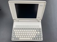
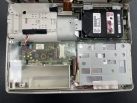
I got a Toshiba T1800 laptop.
The floppy drive had been repaired by replacing the belt.
But the LCD still does not display well.
Even lamp & contrast adjustment potentiometer had been replaced, the characters still can't see clearly,no matter how you adjust the contrast.
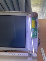
The characters can barely be seenand when viewed obliquely from the top side.
Who knows where the fault might be.
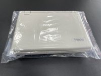
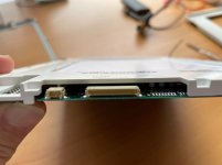
微信图片_20230301135949.jpg微信图片_20230301144119.jpg微信图片_20230301135944.jpg微信图片_20230301135939.jpg微信图片_20230301135924.jpg微信图片_20230301135934.jpg
 
Last edited:
For something like this, I think you have a capacitor (condenser) problem.

Check on the back of the LCD module, and try to find some capacitors that have visible residue next to them.
 
For something like this, I think you have a capacitor (condenser) problem.

Check on the back of the LCD module, and try to find some capacitors that have visible residue next to them.
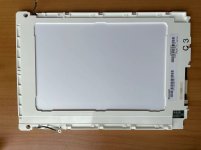
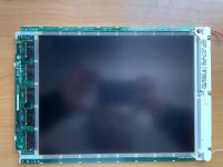
Disassembling the LCD panel is difficult! The circuit board and plastic casing appear to be adhering. Giving up!
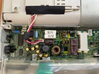
Is the power board the issue? I'll attempt to swap out every capacitor on it. More to come...
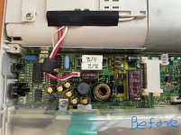
微信图片_20230303135348.jpg微信图片_20230303135357.jpg微信图片_20230303135352.jpg微信图片_20230303135341.jpg微信图片_20230303135433.jpg
 
If there's a very faint image, likely a backlight or backlight-inverter problem (assuming it has one).
 
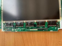
I can see surface mount caps faintly in the fourth image of the LCD you showed on your last post, you need to replace them, it's your issue 100%. Take care of the DC board too, but that won't fix your screen.
 
I can see surface mount caps faintly in the fourth image of the LCD you showed on your last post, you need to replace them, it's your issue 100%. Take care of the DC board too, but that won't fix your screen.
Thx!

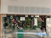
Last night, I changed every capacitor on the DC board, but the problem still exists.
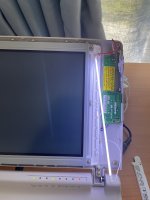
微信图片_20230306113400.jpg微信图片_20230306113413.jpg

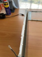
Although it is extremely challenging to separate the LCD glass panel and the circuit board on it, it appears that I had to do that as your suggestion.
I'm really afraid to break the glass panel!
 
You have to remove the plastic from the back. I’ve done this with several SHARP LCD panels, it isn’t too difficult. Just carefully lift it out, may need a bit of persuasion the first time. Just make sure not to bend anything and you should be fine.
 
You have to remove the plastic from the back. I’ve done this with several SHARP LCD panels, it isn’t too difficult. Just carefully lift it out, may need a bit of persuasion the first time. Just make sure not to bend anything and you should be fine.
Thanks a lot!
I got it open. It's realiy the capacitors on the LCD panel that cause the problem.
I will order some capacitor to change them.
to be continue ...
微信图片_20230306130233.jpg微信图片_20230306130107.jpg
 
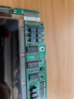
There is your problem! The capacitors with the residue!

I can see surface mount caps faintly in the fourth image of the LCD you showed on your last post, you need to replace them, it's your issue 100%. Take care of the DC board too, but that won't fix your screen.
Also, good eye! I didn't see them before!
 
The curse of the fake imposter tantalums.

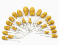
Those style capacitors (thankfully) don't exist anymore. I would recommend using SMD tantalums due to their location.

From your pic, they look to be the exact same values as the ones I replaced on a few projects, 3.3uF at 35v. I used these as replacements.


1206 or 1311 style caps will fit.

You'll want to make sure you clean the area good after you remove those caps because the leaked electrolyte is conductive and corrosive. Regular alcohol doesn't really work that well for cleaning capacitor electrolyte, it just smears it around.

I use this stuff and a little bit on a cuetip cuts through capacitor residue like a hot knife through butter.
 
Wow those are corroded! I hadn’t seen any that bad before. Hope it all goes well, you’re probably going to have a good amount of trouble getting the solder to flow. Good luck!
 
The curse of the fake imposter tantalums.

Those style capacitors (thankfully) don't exist anymore. I would recommend using SMD tantalums due to their location.

From your pic, they look to be the exact same values as the ones I replaced on a few projects, 3.3uF at 35v. I used these as replacements.


1206 or 1311 style caps will fit.

You'll want to make sure you clean the area good after you remove those caps because the leaked electrolyte is conductive and corrosive. Regular alcohol doesn't really work that well for cleaning capacitor electrolyte, it just smears it around.

I use this stuff and a little bit on a cuetip cuts through capacitor residue like a hot knife through butter.
thx!
I have ordered some tantalum capacitor (3.3uF at 35v,10uf at 16V).
SMD capacitor is difficult to soldering for me.
20230306221459.png
 
thx!
I have ordered some tantalum capacitor (3.3uF at 35v,10uf at 16V).
SMD capacitor is difficult to soldering for me.
View attachment 1253808

SMD caps actually aren't that difficult. Just use some solder paste on both pads and set the cap in between them with tweezers, then heat the solder paste one side at a time. I'd recommend low melt solder, the 183C type. There's a brand called "Mechanic" that sells really good solder paste in a syringe, which makes it super easy to apply in the small amounts needed.

Using normal solder wire from a roll is a lot more difficult due to the molten solder wanting to move the capacitor. Solder paste provides a bit of suction to keep the capacitor in place.
Maybe SMD caps next time
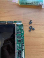
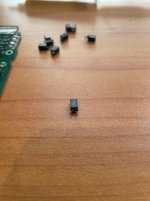
Today I cleaned the PCB of LCD panel.
As the Board was originally made with high melt solder, it was difficult to remove the defective caps from it.
Now just wait for today's delivery of the tantalum capacitors and cleaner for electrical parts.

微信图片_20230307164100.jpg微信图片_20230307164107.jpg
 
Good job getting them off. I usually just grab them with pliers and flex them side to side slowly until they break from fatigue, takes a lot less time.
 
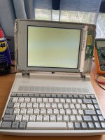
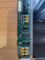
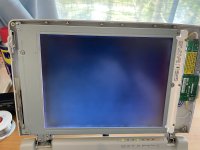
All caps has been replaced,but the lcd
still has problem just like before .
Any advice?
329385B0-F74F-4E63-A35F-7E41B7451D44.jpegFED61999-DDBE-4272-8A9E-A2A19FF9C499.jpeg
 
I would double check the circuity that adjusts the contrast personally. But given everything done so far, its just a hunch.
 
That screen looks similar to an early Powerbook screen. Check to see if you have high voltage to the screen, I believe it's either 12, 25 or 50 volts. If that voltage source is missing, the screen won't work. IIRC, the voltage is present on the ribbon cable going to the screen.
 
Yes, that issue is indicative of no signal being sent to the actual pixels in the screen. This could mean that the LCD driver board has an issue, the computer isn’t starting a proper display output, or it’s missing a voltage that it needs.
 
Back
Top