pavery
Experienced Member
In the day, was there a popular & practical add-on that gave a cassette-based Model 1 the RS-232 function without buying an Expansion Unit?
Thanks
Philip
Thanks
Philip
| VCF West | Aug 01 - 02 2025, | CHM, Mountain View, CA |
| VCF Midwest | Sep 13 - 14 2025, | Schaumburg, IL |
| VCF Montreal | Jan 24 - 25, 2026, | RMC Saint Jean, Montreal, Canada |
| VCF SoCal | Feb 14 - 15, 2026, | Hotel Fera, Orange CA |
| VCF Southwest | May 29 - 31, 2026, | Westin Dallas Fort Worth Airport |
| VCF Southeast | June, 2026 | Atlanta, GA |


1000 REM -LORENZ ATTRACTOR FOR TRS-80 LEVEL II BASIC
1010 REM -REQUIRES STAGE 1 MACHINE CODE GRAPHICS ROUTINES FOR
1020 REM -VGA VIDEO CARD B. WWW.GLENSSTUFF.COM
1030 POKE 16527,112: I=16526: X1=124: Y1=131: X2=138: Y2=145
1040 L2=203: POKE 28673,63: POKE I,64: A=USR(48)
1050 ST=0: C=0.01: S=10: R=28: B=2.67: X=1: Y=0: Z=20
1060 REM -COMPUTE, SCALE AND PLOT ATTRACTOR TO VGA SCREEN
1070 DX=(-S*X)+(S*Y): DY=(R*X)-Y-(X*Z): DZ=(-B*Z)+(X*Y)
1080 X=X+(DX*C): Y=Y+(DY*C): Z=Z+(DZ*C)
1090 PX=(X*12)+320: PY=(-Z*8)+450: IF ST=1 THEN 1110
1100 POKE I,X1: A=USR(PX): POKE I,Y1: A=USR(PY): ST=1
1110 POKE I,X2: A=USR(PX): POKE I,Y2: A=USR(PY)
1120 POKE I,L2: A=USR(0): REM -CALL DRAWLINE -(X2,Y2)
1130 GOTO 1070 : REM -NEXT ITERATION There's various bits of info re serial printing from the cassette port in TRS8BIT. Vol. 1 Issue 2 page 3, and Vol 7, issue 2 page28.
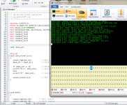
So LPRINT and LLIST will just "print" to the serial port. My main use for this will be for documenting my BASIC program listings - I'll be able to simply capture the output from the line printer commands with any decent terminal program on my PC.
.... but less so for bidirectional communication.
I have read on the internet that +5V was available at pin 3 of the Model 1's expansion port only on early versions of the main PCB. Is that true?
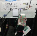
Forgot to mention that my design supports that in hardware too. On the read side at port 0x37E8, the PIC UART has command of the full data bus, not just the four printer status lines D4-D7. An open-drain I/O pin (RA4) of the PIC is wired to the expansion bus interrupt line. That provides a means of signalling to the computer that a received character is ready to be read at 0x37E8. The TRS-80 can signal back to the UART that it has copied the character simply by writing back to port 0x37E8, though that generally won't be necessary. For the RS-232 port I have implemented in hardware lines RTS, CTS, TX and RX and I have assigned two DIP switch positions for configuring the mode of operation. The basic line-printer mode (that I have shown here) is/will just be a dumb transmitter only on TX with no handshaking. The other three programmable modes are left available for whatever one-way or two-way communications protocols I may wish to implement in the future.
Micromint produced a SBC based on HD64180 called smart spooler (I have 2).Thanks Eudimorphodon, that was the hint I needed. Further research shows Micromint produced the COMM-80 interface which included RS-232 & parallel printer port. This article describes the board in detail.
Philip
The +5v is only supposed to be there on Level I Model Is; with the Level II upgrade they were supposed to cut the trace and convert it to a ground. I'm not sure there was ever a really good explanation for the change, but that's how it is. You should assume that there's no power feed available from the edge connector on most real Model Is. (I mean, I guess even if it is there because you have a Level I Model I it's not going to do you any good with a peripheral that emulates an printer port, given Level I BASIC doesn't have LPRINT/LLIST commands. Only officially supported printer for that machine was the wacky "Screen Printer" that DMA'ed data straight from screen memory.)
(To really make things confusing, the "buffer cable" mod for the Expansion Interface uses one of the pins on the EI's connector to supply the voltage to power the buffer back the other way, creating opportunities for shorting things if you use the wrong cable. Fun stuff.)
FWIW, if you really want to have full RS-232 bidirectional capability in your hardware it might be worth at least considering making this device able to emulate the actual port-I/O layout of the official RS-232 card in addition to your "pretending to be the parallel port" scheme.
(I'm pretty sure there was an article in 80 Micro describing how to route the parallel printer output in the Expansion Interface to be shadowed out the serial port to dispense with the need for a serial printer driver, so precedent certainly exists for making double-duty out of the single port.)
For minimal compatibility you'd probably just need to implement data in/out on port EB, (simulated?) status lines on E8, and some synthetic version of the UART status on EA. I *think*, but won't swear to this, that the Model I's implementation of the serial port was entirely polling driven, with a software loop just scraping the UART status flags to see if an incoming character was available; the expansion connector inside the EI does have an interrupt line but I don't think it was used by the card?
I guess this only really matters if you want to use existing TRS-80 terminal software, if you just want to write your own then whatever scheme you like should do.
It cost nothing to connect an otherwise unused open-drain I/O pin of my PIC UART to the INT line.
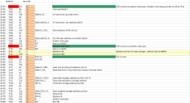
I am going to have to further complicate my hardware with a latch to assert INT*. The latch will be set by the UART after each received a character, and will be cleared by RD*-0x37E8.
10 FOR X=1 TO 37: READ D: POKE 31743+X,D: NEXT X
20 DATA 237,86,62,195,50,18,64,33,19,124,34,19,64,251,201
30 DATA 243,201
40 DATA 0,128
50 DATA 229,197,33,232,55,78,42,17,124,113,35,34,17,124,193
60 DATA 225,251,201
100 REM -ENABLE ISR
110 POKE 16527,124: POKE 16526,0: A=USR(0)
200 CLS: REM -PRINT CHAR TO SCREEN
210 MP=PEEK(31761): IF MP=0 THEN 210
220 B1=PEEK(31761): B2=PEEK(31762)
230 MS=B1+(B2*256)-1
240 CH=PEEK(-(65536-MS)): PRINT CHR$(CH);
250 M=PEEK(31761): IF M=MP THEN 250
260 MP=M: GOTO 220


