• Please review our updated Terms and Rules here

TRS-80 Model I Monitor troubleshooting

mdhokie

New Member
Joined
Apr 18, 2023
Messages
9
I bought a TRS-80 Model I (Level II) and monitor at the VCF East event this weekend. Awaiting purchased power supply to test/troubleshoot the computer, but the monitor definitely doesn't work. The 1A fuse in the power supply was blown; replaced it and blew again immediately so troubleshooting the circuit board using the Sam's guide found here: https://www.heinpragt.com/retro_com...rFacts - Model I (1985)(Howard Sams)(pdf).pdf

I went through the troubleshooting guide, which mentioned only diode CR101 and capacitor C110 as potential causes for blown fuse. Diode check on CR101 looked good, and capacitor was correct value on capacitor meter and not shorted, so moved on to testing all other capacitors and diodes, and resistance measurements.

My first question is about the resistance measurements on page 60 of the PDF (page 18 of the original CSCS3-B document). It gives a table of pin numbers plotted against diode and other part leads, with expected resistance values. The rows are for transistor and other parts, and columns are "Pin" numbers. I must not be understanding the testing methodology, because I can't figure out what any of those Pin numbers correspond to. The only numbered items I can associate with the columns anywhere in the document are:
- the notations 1-6 on page 48 (pdf)/6 (CSCS3-B) with associated voltage readings (but I don't see anything but no-connect from those voltage points to the transistor leads)
- notations 5,7,11 page 55/13 (this can't be right since then there would be two Pin 5, plus where are 8/9/10?)
- notations 12-58 on page 57/15 (almost none of these are even the low numbers associated with the resistance table, since it starts with 12)
- the pins that connect to the graphics board (but there are only 12 pins in the connection slots, and the resistance table indicates 13/14 pins)
So what are the "Pin" columns? I was expecting you'd hook one ohmmeter lead to whatever Pin location, and the other lead to the indicated lead on the named component, and check the reading, but I am clearly missing something. Or perhaps one of my conflicting guesses was correct, but my multimeter is not feeding enough power to the resistance check to get through semiconductors?

My second question is about diode readings: I get a valid-looking diode check for most of the CRxx parts (0.5-0.7V) as they sit in-circuit, with the exception of two of them:
- CR7 (get .1V diode check either direction, measure constant 155 ohm each direction)
- CR19 (get .1V diode check either direction, measure constant 170 ohm each direction)
Are these values expected because I'm doing in-circuit measurement and other nearby components are rerouting the applied voltage, or are these problematic? I have desoldering equipment but I don't want to start mucking with that until I've done all the tests I can do with the circuit intact.

Thanks for any help.
 
Update on diode readings:
- CR7 is indeed parallel to a resistor in the circuit which would explain the resistance in each direction, and isn't shorted or it would be 0 ohms
- I removed CR19 from the circuit and got a good diode check voltage, so I put it back.

Every resistance reading I make is still wrong according to the chart. The ones that are supposed to be 0 ohms are coming up in the kiloohms, tens of ohms expected readings are also in kiloohms.
 
I would forget the charts. A lot of these sorts of things are practically useless in fault finding. They more or less came about because people in management didn't understand electronics technology and came to the misplaced belief that fault finding and repair could be performed by a Chimpanzee if they were given a flow chart to follow.

Reality is not like this and most of the real world faults you encounter were not predictable in advance and no flow chart or test sequence was imagined for them in advance, disappointing management because the inescapable conclusion is that the technicians were a lot smarter and would have to be a lot smarter than management ever imagined they would have to be, to make repairs.

Even the original equipment designers could not conceive of every possible fault scenario or component failure mode, and they were x 10 smarter than management in many cases.

The better plan is to study the schematic, figure out how everything works, then formulate a plan to test the most likely suspect parts.
 
Actually, the SAMs manual you have posted is pretty good, because it includes scope waveforms of the important places in the VDU, that schematic is all you need.

If you scoped those locations you would soon see why the VDU is not operating. The common cause of failure and high current consumption is the Horizontal output stage, typically the output transistor, followed by the vertical output stage. You can disconnect the supply feeds to those stages for testing. In the case of the H output stage you can simply disconnect the collector of the H output transistor and see if it stops blowing fuses as an initial test.

Since the H scan stage generates the auxiliary voltages for the CRT, if that gets deactivated, the screen will not light up. If that is working, and you disable the V scan output stage, you will get a bright horizontal line, in that case it pays to have the brightness control turned right down.
 
Last edited:
Be careful! This monitor has a hot chassis, use an isolation transformer or you may blow up your scope or zap yourself.
 
Be careful! This monitor has a hot chassis, use an isolation transformer or you may blow up your scope or zap yourself.

Yes, the best move is to run it from the isolating transformer and also connect its chassis/common to Earth, This converts it into the equivalent of a transformer powered set. This way it will have the same ground potential as the scope and most grounded test instruments, before they are connected.

Some people don't add the earth connection and rely on the test instruments earth grounding it when the earth clip is attached to the chassis/common, but the chassis can have floated up to some unspecified voltage beforehand and then it has to discharge into the test instrument's earth clip. If you don't have a plan to attach a grounded test instrument to it, and only plan to use an isolated tool like a meter, then there is a marginal safety increase by not adding the earth wire because it then requires two points to have skin contact before a current flows, rather than one.

Also note that the addition of the isolation transformer defects the dwelling's ELCB(earth leakage contact breaker), so that adds no safety.

Assuming the HOT chassis set does have its chassis connected to Neutral (and not phase by mistake) the chassis at least is close to ground potential, within a few volts. But you cannot connect an earthed scope probe to that as it injects hum voltages into the measured signal because you have shorted neutral & earth together.

If the power cord or the general purpose outlet is mis-wired, the unit's ground or chassis could be live, then if you clip your scope probe to it, you short phase to ground, or even if you touched it, the ELCB (if working), it would just kill the power as the current rose over 30mA, if not then a major electrocution hazard and The Big Bang when the probe earth touched the chassis, sparks and melting metal, until the current rises far enough over 20A or so to trip the current breaker, or burn out the wire fuse in the old system.
 
If you scoped those locations you would soon see why the VDU is not operating. The common cause of failure and high current consumption is the Horizontal output stage, typically the output transistor, followed by the vertical output stage. You can disconnect the supply feeds to those stages for testing. In the case of the H output stage you can simply disconnect the collector of the H output transistor and see if it stops blowing fuses as an initial test.

Since the H scan stage generates the auxiliary voltages for the CRT, if that gets deactivated, the screen will not light up. If that is working, and you disable the V scan output stage, you will get a bright horizontal line, in that case it pays to have the brightness control turned right down.
Thank you! That sounds like a good place to start. I can definitely do that, and see what happens. I understand basic circuit components, but don't have any experience with CRTs so I don't understand the block-level circuit designs.

Regarding the hot chassis; it's wired to neutral, and I know my outlet is wired correctly, but yeah will confirm that it's actually close to ground before getting any fingers close to it! Because I can't power it up yet without blowing a fuse, it hasn't been an issue as I'm doing all the analysis in a dead board with a multimeter.

Sadly, I'm not sure that I'm equipped to do proper signal analysis if I get past the overcurrent condition. I've always wanted a decent oscilloscope but never had one. I have one of the USB oscilloscopes, but it's only designed for logic board level voltage (I think less than 10V) and I'd probably fry it with the signals coming off the monitor/TV. I'm hoping though that if I can fix the overcurrent condition it will otherwise just work.
 
Disconnected horizontal output (Q101) black wire that went to the high voltage, still blows fuse. So still hunting, but that definitely seems like a useful test. That was my last spare fuse though, so I need to go buy some fuses before I can do any more disconnect/fuse experiments with the vertical output. I assume I'll continue to leave the H output disconnected just in case there's multiple faults, until I can get it to power on without blowing fuses. Thanks for the tip!
 
Got more fuses.

@Hugo Holden : Today I tried disconnecting the white wire from above the resistor that says "vert out" that goes to the tube. Not sure if this was what you meant by disabling the vertical output, but it was an effective test. With both that and the horizontal output wire removed, I can plug in and turn on the switch without blowing a fuse. It did seem to perform a lobotomy on most of the board however. From the Sam's book I referenced, PDF page 48: Pin 1 (the 11.1V reference point) was at 6.25V; Pin 2 (the 85.9V reference point) was at 143V, and all the other low voltage points were at 0. No humming and no tube lighting up, but neither did the fuse blow, so that's a start. If I understand what you said earlier, I should now try re-connecting the horizontal output wire and seeing what happens?
 
With horizontal output wire reconnected, tube does indeed light up, and I see the lower voltages are present and roughly the correct values. Hey that's progress! Now to figure out what's going wrong with the vertical output...
 
OK I did a lot more troubleshooting and have to admit I'm stumped. Anybody understand this design enough to know what's going on? I have lots of information though:

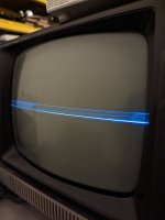
- I have the wire from post E27 disconnected (one side of the deflector yoke vertical coil) to keep it from blowing the fuse. Everything else connected. The tube powers up, and if I have the brightness turned up I see a horizontal white line. I keep it turned down to avoid burning in the tube.

- Deflector yoke vertical coils resistance seems good and matches the nominal resistance indicated in the manual (19-20 ohm from the wire I disconnected E27, to the other wire going to E28 on the board).
- Voltage at E27 (not connected to the yoke): 13.6V
- Voltage at E28 (connected to yoke, but circuit open/not complete): 1.5V
- This large difference in voltage might be just because it's an open circuit with no load; I can't connect without blowing the fuse so I don't know if this big potential difference is what's causing the large current draw that's blowing the fuse.

- Voltages per Sam's PDF page 48, measured vs nominal from the document:
-- 1: 11V (nominal 11.1V)
-- 2: 90V (nominal 85.9V)
-- 3: 23.1V (nominal 19.0V) -- a little high
-- 4: 22.7V (nominal 16.2V) -- high
-- 5: 19.5V (nominal 18.6V)

- Oscilloscope traces for vertical output, from the Sams PDF page 44:
-- The signal off the output of Q3 has a distinct waveform, and looks good both before and after C35. On the other side of the resistor R38, however, the signal is gone. I get a flat 11V with no distinct waveform. Both the base and collector of Q4 have a flat signal at a fixed voltage.
-- Voltages around Q4 are odd, compared to the big circuit diagram: the base voltage is about right (12-13V) but it has a lower voltage than the collector or emitter (each about .6V diode's worth higher than the base). In the circuit diagram, it's the opposite: the base is supposed to be a higher voltage than the collector or emitter.

- I did lots of component checks around the suspect area (vertical output signal)
-- I removed all of the transistors Q4, Q5, Q6, Q7, Q8, Q9 from the circuit board and did diode tests in all directions; all tested fine
-- I did diode checks on all diodes in the vertical output circuit, CR6, CR7, CR8, CR9. Some I tested in-circuit; the ones that didn't get a clear result I removed from the circuit and they tested fine in isolation.
-- I removed and tested capacitors C38, C39, C40, C41, C42, C43, C44. All seemed close to nominal capacitance values (although my multimeter actually shows a higher number than rated sometimes; I suspect that's a multimeter issue though and not indicative of failure) and none were shorted.
 
PXL_20230430_213122353.jpg

I did another experiment, because I was unsure whether the no-load of having the vertical deflector yoke disconnected was affecting voltages etc. in the circuit. So I hooked up a 1k resistor in between the disconnected wire and E27, to give it at least a little load without allowing enough current to blow the fuse. On the screen, instead of a flat line, I instead see a little vertical spread (see picture).

With this modification in place, I made the following observations:
- The voltages that seemed high (locations 3 and 4) lowered by a few volts (more like 20V rather than 22/23V). So the higher-than-nominal voltages were probably a symptom of no load.
- Q4 voltages became less weird with this setup. The base was around 15V, and the emitter/collector were lower voltages than the base. So this weirdness was also probably an effect of no load.

Other observations:
- The oscilloscope readings in the Sam's manual I think were assuming a test pattern generator signal, which I don't have, so any assumptions I made about the waveforms may have been incorrect.
- I no longer trust my oscilloscope readings. I think the capacitance/resistance of the oscilloscope leads are changing the signal. When the oscilloscope was hooked up to Q4 base with this modification, the image on the CRT that I included disappeared, and instead was replaced by a slowly strobing horizontal line going upwards before going blank and starting over again.
 
PXL_20230430_225946849.jpg


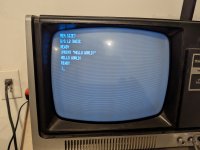
OK. So after all that troubleshooting I just reconnected the vertical deflection yoke and tried again. And it works now. So what did I learn? Nothing. I still have no idea what caused the fuses to blow initially. None of the solder joints I reworked looked bad, I saw no shorts anywhere, but...now it works. Thanks for the tips.
 
I have the RCA labeled version of the same set with the tuner and a big issue for me was the multi-stage capacitor had failed and was popping the fuse on cold start but would come up when load limited. I also had really weird deflection because it was extremely leaky as well.
 
I bought a TRS-80 Model I (Level II) and monitor at the VCF East event this weekend. Awaiting purchased power supply to test/troubleshoot the computer, but the monitor definitely doesn't work. The 1A fuse in the power supply was blown; replaced it and blew again immediately so troubleshooting the circuit board using the Sam's guide found here: https://www.heinpragt.com/retro_computers/trs80_files/Sams ComputerFacts - Model I (1985)(Howard Sams)(pdf).pdf
I clicked on your link, but all I got was "404" dead link, and can't find anything about TRS-80 there anymore!
 
View attachment 1256536


OK. So after all that troubleshooting I just reconnected the vertical deflection yoke and tried again. And it works now. So what did I learn? Nothing. I still have no idea what caused the fuses to blow initially. None of the solder joints I reworked looked bad, I saw no shorts anywhere, but...now it works. Thanks for the tips.
I just wanted to thank you for sharing your journey on this! I have the exact same problem with a TRS-80 Model 1 (RCA) monitor - I've been going through all of the same steps without much luck (still blowing fuses). I'm relatively new to high-voltage AC stuff so being extra careful and frankly some of these concepts (like the use of isolation transformers) is completely new to me, but really want to learn this stuff. Luckily I have another monitor that works so I can at least swap some parts to hopefully narrow down the issue.
 
Back
Top