• Please review our updated Terms and Rules here

Unidentified Turbo XT Clone has F/C stuck low

What is the speed rating of your DRAM? 80 nsec would be optimal, though you could probably get away with selected 120 nsec ones.
Right now I’ve got 2 banks of M5M4256P at 15ns and 2 banks of HM4864P-2 (15ns).

Laying around I have two 8ns 256 banks, but nothing faster than 15ns for 64.

I have reseated every chip on the right hand side of the motherboard and now it’s a lot stabler. It can usually do 6-7 rounds of Ruud’s diagnostic ROM without too many trouble. Sometimes I get an address error on bank 3 (513KB - 576KB) but it happens pretty rarely.

If you think it’s ideal to use 8ns, I can swap Bank 0 and Bank 1 with the 8ns ones.

Still getting the IRQ0 issue. Keyboard works after first pass (I think that’s something with my Model M) but I have just noticed that the ROM tests on the top right fail most of the times and some only pass occasionally after multiple rounds. I am using Ruud’s Diagrom in a 27256, if it helps.

EDIT: Put the 8ns 256s in, since I got another address error on a low address (77KB), let’s see if it helps.

EDIT2: Worked fine for an hour or so then the 77KB/125KB error came back, this time even with a new set of RAM chips. I have only reflowed bits 4-7 of Bank 0, should I try reflowing 0-3 as well?
 
Last edited:
Does this mean that the first 0-32Kb addresses are parallelised over the 9 chip's A0?
'Parallelised'? - Yes.
A0? - No.
The cells within each chip are in the form of a matrix. To select a cell, for either a write or read operation, a row address is provided, then a column address. See the fictional example at [here].

The board is rock solid when working in 4.77MHz mode. The IRQ0 error is still there, though.
Progress.

Maybe one of the buffers not being able to tolerate the faster speeds?
You have been swapping chips between the two boards. We know (because of the clock issue) that the two motherboards are not identical. I wonder if a slower rated part was swapped in (e.g. 74LS999 in place of 74S999).

But chips can fail in ways that can make them temperature sensitive, that can make them speed sensitive, that can make them intermittent, ...

BTW, slapping a fan over the 8253 and 8259 alleviates/solves the issues somehow.
The fan is not need on a good motherboard. You are homing in on a problem cause. You don't have spare 8253 and 8259 ?

A fan is not very directional. Maybe the temperature sensitive component is a nearby chip. In your situation, I would be using non-conductive freeze spray to home in on the chip.
 
The board is rock solid when working in 4.77MHz mode. The IRQ0 error is still there, though.
Anyway the SuperSoft / Landmark ROM does not report the IRQ0 error ...
Leave that one with me. Ruud's Diagnostic ROM is based on the SuperSoft/Landmark ROM, and so I expect the same behaviour for certain tests. For the IRQ0 test, I will compare the programming code.
 
What is the speed rating of your DRAM? 80 nsec would be optimal, though you could probably get away with selected 120 nsec ones.
Right now I’ve got 2 banks of M5M4256P at 15ns and 2 banks of HM4864P-2 (15ns).
As rough comparisons:
- The photo of the PIM-TURBO, an 8 MHz XT-clone motherboard, at [here], shows 150 ns RAM chips fitted.
- The user manual for DTK's PIM-TB10-Z, a 10 MHz XT-clone motherboard, specifies 120 ns (implied is 'or faster').
- A 10 MHz XT-clone motherboard that I have, is fitted with 120 ns RAM chips.

Laying around I have two 8ns 256 banks, but nothing faster than 15ns for 64.
Probably 80 ns and 150 ns.
The tables at [here] are expected to inform you.
 
... but I have just noticed that the ROM tests on the top right fail most of the times and some only pass occasionally after multiple rounds.
Looking at the photo of your motherboard in post #1, I see six ROM sockets, of which only one is populated (for BIOS ROM, or diagnostic ROM).

I am guessing that your motherboard is configured for 8 KB sized ROM's. The address mapping is probably like that for IBM 5150:

One ROM at FE000. (Used for BIOS ROM, or diagnostic ROM.)
One ROM at FC000. (Optional ROM BASIC - ROM #4 of 4)
One ROM at FA000. (Optional ROM BASIC - ROM #3 of 4)
One ROM at F8000. (Optional ROM BASIC - ROM #2 of 4)
One ROM at F6000. (Optional ROM BASIC - ROM #1 of 4)
One ROM at F4000.

Ruud's Diagnostic ROM (RDR) and the SuperSoft/Landmark Diagnostic ROM (SLDR) cannot reliably detect an empty ROM socket.

For example, in the IBM 5150, the ROM socket at address F4000 is empty; sometimes, RDR and SLDR will pass the 'Check ROM at F4000' test, and sometimes fail it.

In your case, where the F4000 through FC000 ROM sockets are empty, ignore the results of the 'Check ROM at Fxxxx' tests.
 
EDIT2: Worked fine for an hour or so then the 77KB/125KB error came back, this time even with a new set of RAM chips. I have only reflowed bits 4-7 of Bank 0, should I try reflowing 0-3 as well?
I cannot see how a soldering problem would result in stable operation at 4.77 MHz, and unstable operation at 8 MHz.

The instability can lead you to wrong conclusions. My car will not start. I kick the car's front right tire then get back in my car. The car starts at first attempt. Kicking the tire was the fix.
 
'Parallelised'? - Yes.
A0? - No.
The cells within each chip are in the form of a matrix. To select a cell, for either a write or read operation, a row address is provided, then a column address. See the fictional example at [here].

You have been swapping chips between the two boards. We know (because of the clock issue) that the two motherboards are not identical. I wonder if a slower rated part was swapped in (e.g. 74LS999 in place of 74S999).

But chips can fail in ways that can make them temperature sensitive, that can make them speed sensitive, that can make them intermittent.

The fan is not need on a good motherboard. You are homing in on a problem cause. You don't have spare 8253 and 8259 ?

A fan is not very directional. Maybe the temperature sensitive component is a nearby chip. In your situation, I would be using non-conductive freeze spray to home in on the chip.
Excellent explanation thanks. Your site literally has everything on it!

Just checked the two boards and I don't see any difference when it comes to S/LS chips between the two boards.

I do, the spares have the same issues, so it's nothing related to the 8253 and/or 8259, I think.

I am not sure that the fan is really helping - maybe it's placebo effect. The board can run fine for an hour or so without any fan when it so desires (like last night) while immediately giving out errors even with the fan on it (like right now).

I do have non-conductive freeze spray and everything is just so random that it's very difficult to understand if you had somehow cooled the right IC or if the board has just randomly decided to work for 6 passes straight with no additional cooling.

Leave that one with me. Ruud's Diagnostic ROM is based on the SuperSoft/Landmark ROM, and so I expect the same behaviour for certain tests. For the IRQ0 test, I will compare the programming code.
Indeed, that's why I have reported this discrepancy to you - pretty weird.

As rough comparisons:
- The photo of the PIM-TURBO, an 8 MHz XT-clone motherboard, at [here], shows 150 ns RAM chips fitted.
- The user manual for DTK's PIM-TB10-Z, a 10 MHz XT-clone motherboard, specifies 120 ns (implied is 'or faster').
- A 10 MHz XT-clone motherboard that I have, is fitted with 120 ns RAM chips.


Probably 80 ns and 150 ns.
The tables at [here] are expected to inform you.
Pretty sure this motherboard's originally had 150ns chips fitted to it back then, which should match the other 8MHz turbo boards.

Looking at the photo of your motherboard in post #1, I see six ROM sockets, of which only one is populated (for BIOS ROM, or diagnostic ROM).

I am guessing that your motherboard is configured for 8 KB sized ROM's. The address mapping is probably like that for IBM 5150:

One ROM at FE000. (Used for BIOS ROM, or diagnostic ROM.)
One ROM at FC000. (Optional ROM BASIC - ROM #4 of 4)
One ROM at FA000. (Optional ROM BASIC - ROM #3 of 4)
One ROM at F8000. (Optional ROM BASIC - ROM #2 of 4)
One ROM at F6000. (Optional ROM BASIC - ROM #1 of 4)
One ROM at F4000.

Ruud's Diagnostic ROM (RDR) and the SuperSoft/Landmark Diagnostic ROM (SLDR) cannot reliably detect an empty ROM socket.

For example, in the IBM 5150, the ROM socket at address F4000 is empty; sometimes, RDR and SLDR will pass the 'Check ROM at F4000' test, and sometimes fail it.

In your case, where the F4000 through FC000 ROM sockets are empty, ignore the results of the 'Check ROM at Fxxxx' tests.
Cool, thought that was the case but I wasn't sure.

I cannot see how a soldering problem would result in stable operation at 4.77 MHz, and unstable operation at 8 MHz.

The instability can lead you to wrong conclusions. My car will not start. I kick the car's front right tire then get back in my car. The car starts at first attempt. Kicking the tire was the fix.
I thought that if a certain chip worked harder it would heat up more (and that it is indeed the case with many chips in 8MHz mode) and that could cause thermal expansion on some pins making it lose contact. Anyway this time it gave issues on cold boot as well so I am not really sure what we are looking for here...

I am just very confused on which ICs on the board take part of the "Data" part of the tests and which take care of the "Address" part. With the clock issue the thing was quite easy (8284 = clock generator), meanwhile with the RAMs even while looking at the schematics I am not quite getting the full picture.
 
Last edited:
Sorry for the double post, but I *think* I have solved it. I have replaced the 8288, which was a very nice ceramic one made by NEC with an 82C88 made by UMC and… I think everything is working? The ceramic one got VERY hot after a while.

It has sustained multiple rounds (I think up to 10-15) on SuperSoft/Landmark while with Ruud’s Diagnostic 3.9 it mathematically crashes every time it completes Round 6 of the RAM Address test with address 0KB. I am not sure if it’s a bug or something but the Landmark one doesn’t show anything like that and it keeps going.

Another suggestion for modem7 for a future version of Ruud’s - the ROM skips the stuck keyboard test also on subsequent rounds even if the KBC test passes on those rounds. Maybe it should only skip it if it has failed in the test immediately before it and not globally?

I will keep testing it tomorrow but I am hopeful that it’s almost fixed for good.

Thanks again for all your help!
 
Sorry for the double post, but I *think* I have solved it. I have replaced the 8288, which was a very nice ceramic one made by NEC with an 82C88 made by UMC and… I think everything is working? The ceramic one got VERY hot after a while.
I will keep testing it tomorrow but I am hopeful that it’s almost fixed for good.
Yes, early days. I have been in this kind of a situation many times before, only to have the problem return later. It is very frustrating. Cross your fingers and your toes.

It has sustained multiple rounds (I think up to 10-15) on SuperSoft/Landmark while with Ruud’s Diagnostic 3.9 it mathematically crashes every time it completes Round 6 of the RAM Address test with address 0KB. I am not sure if it’s a bug or something but the Landmark one doesn’t show anything like that and it keeps going.
Have a read of [this] to gain an appreciation of an addressing problem.

The SuperSoft/Landmark Diagnostic ROM (SLDR), and early versions of Ruud's Diagnostic ROM (RDR) do not check for RAM related addressing problems. The POST of the IBM BIOS looks for some, and later versions of RDR do.

I can create one by going to my IBM 5160 motherboard of type 256-640KB, pulling out a 41256 chip out of bank 0, and replacing it with a 4164. SLDR will completely pass. Version 3.9 of RDR will pass the RAM data test, but then fail on the RAM addressing test.

Sometimes an addressing problem happens in a RAM chip, sometimes the motherboard is the cause.

( I have yet to improve RDR. There are some addressing problems it does not detect. )
 
Another suggestion for modem7 for a future version of Ruud’s - the ROM skips the stuck keyboard test also on subsequent rounds even if the KBC test passes on those rounds. Maybe it should only skip it if it has failed in the test immediately before it and not globally?
Yes, I will do that.
 
I will keep testing it tomorrow but I am hopeful that it’s almost fixed for good.
Is the 'Checking interrupt IRQ0' test in Ruud's Diagnostic ROM (RDR) version 3.9 still failing ?

I ended up comparing the source code for that test against the source code for the equivalent test in the SuperSoft/Landmark ROM (SLDR).
The only differences were:
1. RDR stores the record of the 8259's ISR in unused MDA/CGA video RAM. SLDR stores the record at address 00400h.
2. The order of some of the setup code is different.

They are not differences that I expect a problem to result from (but sometimes, these things can be quite subtle).

Of note, the 8253 is being configured identically, and the delay values are identical.
 
Yes, early days. I have been in this kind of a situation many times before, only to have the problem return later. It is very frustrating. Cross your fingers and your toes.


Have a read of [this] to gain an appreciation of an addressing problem.

The SuperSoft/Landmark Diagnostic ROM (SLDR), and early versions of Ruud's Diagnostic ROM (RDR) do not check for RAM related addressing problems. The POST of the IBM BIOS looks for some, and later versions of RDR do.

I can create one by going to my IBM 5160 motherboard of type 256-640KB, pulling out a 41256 chip out of bank 0, and replacing it with a 4164. SLDR will completely pass. Version 3.9 of RDR will pass the RAM data test, but then fail on the RAM addressing test.

Sometimes an addressing problem happens in a RAM chip, sometimes the motherboard is the cause.

( I have yet to improve RDR. There are some addressing problems it does not detect. )

Yep, I am watching it closely.

I was thinking about the "Ruud's Diagnostic ROM runs entirely from CGA memory" thing, and I was wondering... maybe it runs out of CGA memory after 5 rounds? Because the screen gets garbled with some blue characters, and using another CGA card I have (partially broken) gives a "RAM - Data error" on 551KB which I don't have at all on the other CGA card.

Maybe that's why Landmark/Supersoft wasn't giving me any issues after so many passes? Maybe the issue lies on the CGA card, instead of the MB's RAM itself?

Yes, I will do that.
Cheers!

Is the 'Checking interrupt IRQ0' test in Ruud's Diagnostic ROM (RDR) version 3.9 still failing ?

I ended up comparing the source code for that test against the source code for the equivalent test in the SuperSoft/Landmark ROM (SLDR).
The only differences were:
1. RDR stores the record of the 8259's ISR in unused MDA/CGA video RAM. SLDR stores the record at address 00400h.
2. The order of some of the setup code is different.

They are not differences that I expect a problem to result from (but sometimes, these things can be quite subtle).

Of note, the 8253 is being configured identically, and the delay values are identical.
Yep, still failing in RDR and still working in Landmark/SuperSoft.

Again, the only different thing here is the memory used, in this case the CGA card's video RAM. Maybe my clone has less CGA RAM than expected and it somehow gets filled very quickly? Or maybe part of it is somehow borked?

EDIT: TOPBENCH freezes on a black screen with the F/C pin back in the socket, even when on LOW. Landmark 2.0 and 6.0 work fine (even if it doesn’t change the MHz after turbo. It just beeps faster). I have started wondering if the CGA is borked but I only have another one which outputs a black screen and another one which is partly failing. Putting an EGA card in makes the system not boot (how?) while a VGA card will let it boot but it won’t boot from floppies anymore. What the heck is going on here? RDR works fine for 5 passes as always.
 
Last edited:
Is the 'Checking interrupt IRQ0' test in Ruud's Diagnostic ROM (RDR) version 3.9 still failing ?
Yep, still failing in RDR and still working in Landmark/SuperSoft.

Again, the only different thing here is the memory used, in this case the CGA card's video RAM. Maybe my clone has less CGA RAM than expected and it somehow gets filled very quickly? Or maybe part of it is somehow borked?
Before RDR uses the subject area of MDA/CGA RAM, RDR tests it. If the RAM is non-existent or tests bad, RDR halts.

If the subject RAM passes RDR's test, and RDR starts using it, and the RAM is intermittently bad, that is definitely a problem for RDR. But I would expect crashes, because at some point, a corrupted return address would be read from the stack.

Further investigation is still on my to-do-list. I have some 'turbo' XT-clone boards in storage. Maybe I can reproduce the symptom.

If not, maybe I produce a test version of RDR for you, one that duplicates exactly the IRQ0/INT0 test code in the SLDR, and see if that RDR then successfully runs the IRQ0/INT0 test code on your motherboard. If it does run successfully, we put it down to some strange timing issue, and leave it at that.

Putting an EGA card in makes the system not boot (how?) while a VGA card will let it boot but it won’t boot from floppies anymore. What the heck is going on here? RDR works fine for 5 passes as always.
Those are not passes. The RAM address test has two parts, the first part taking a while to execute. Although there a progress dots that show the user that something is happening, I decided to add a count-down-to-zero so that the user knows how far off the test is to completion. The initial count is a count of 16 KB blocks. So if conventional RAM is 640 KB sized, that is 40 blocks of 16 KB to be processed, and the initial number displayed is 40, and the displayed number is decremented as each block is done.

There is an addressing problem somewhere. When the oscilloscope (a logic probe is okay too) arrives, you will be a position to try TEST6065 at [here]. That may allow you to detect an address bit stuck HIGH or LOW somewhere. An ISA slot is the first place to check that the address bits are toggling. After that, the lack of a circuit diagram for your motherboard makes things problematic, but you should be able to map out the associated address driver circuitry.

Tried bank 0 operation only ? (Chips in other banks removed.)
 
Last edited:
Before RDR uses the subject area of MDA/CGA RAM, RDR tests it. If the RAM is non-existent or tests bad, RDR halts.

If the subject RAM passes RDR's test, and RDR starts using it, and the RAM is intermittently bad, that is definitely a problem for RDR. But I would expect crashes, because at some point, a corrupted return address would be read from the stack.

Further investigation is still on my to-do-list. I have some 'turbo' XT-clone boards in storage. Maybe I can reproduce the symptom.

If not, maybe I produce a test version of RDR for you, one that duplicates exactly the IRQ0/INT0 test code in the SLDR, and see if that RDR then successfully runs the IRQ0/INT0 test code on your motherboard. If it does run successfully, we put it down to some strange timing issue, and leave it at that.


Those are not passes. The RAM address test has two parts, the first part taking a while to execute. Although there a progress dots that show the user that something is happening, I decided to add a count-down-to-zero so that the user knows how far off the test is to completion. The initial count is a count of 16 KB blocks. So if conventional RAM is 640 KB sized, that is 40 blocks of 16 KB to be processed, and the initial number displayed is 40, and the displayed number is decremented as each block is done.

There is an addressing problem somewhere. When the oscilloscope (a logic probe is okay too) arrives, you will be a position to try TEST6065 at [here]. That may allow you to detect an address bit stuck HIGH or LOW somewhere. An ISA slot is the first place to check that the address bits are toggling. After that, the lack of a circuit diagram for your motherboard makes things problematic, but you should be able to map out the associated address driver circuitry.

Tried bank 0 operation only ? (Chips in other banks removed.)
Sorry it took me a bit of time to get back, but I didn't have time to properly test everything you asked me until now.

I have a consistent pattern here, with my "good" (not so sure it is, now) CGA card, RDR always does 5 passes then crashes with graphical artifacts.

With my half-broken ATi CGA card, it usually fails at "Testing RAM - Data" on random (either 0-64KB or >510KB) addresses.

Using only bank 0 makes no difference - either by jumper (the jumper next to the RAM forces Bank 0 only) or by removing all the chips.

I have ran the TEST6065 and A0-A8 are pulsating "equally" (HIGH and LOW are equally bright) while the rest of the addresses have a brighter HIGH led, but LOW can still be faintly seen, so I guess they are actually toggling. I am not sure where XAs are located but I have probed randomly around and I can see a lot of 74s pulsating.

Oh, and IRQ0 started failing again in SLDR as well - not sure what's going on with that.
 
Last edited:
So in the meanwhile I have repaired my other CGA card and it gives the same symptoms as the others.

The system is perfectly stable at 4.77MHz and it works as expected - as soon as I turbo, all hell breaks loose. I *think* I can see an improvement by placing a fan under the dip switches but everything behaves so erratically that it’s very difficult to be sure of anything.

From my LA I can see the EFI signal bounces between 8 and 12 MHz. CLK is a stable 8MHz. Since I don’t have another turbo board to double check, I am not sure if that’s expected behaviour or not.
 
The system is perfectly stable at 4.77MHz and it works as expected - as soon as I turbo, all hell breaks loose.
From my LA I can see the EFI signal bounces between 8 and 12 MHz. CLK is a stable 8MHz.
You indicated earlier that you have a "Salaea 24MHz" logic analyser (LA). A 24 MHz sampling frequency is unsuitable for measuring your EFI signal, which is 24 MHz. Has your oscilloscope arrived yet?

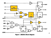
With F/C at HIGH (i.e. use EFI as input), per the 8284 diagram below, CLK is simply the EFI frequency divided by three. If EFI was really 'bouncing' between 8 and 12 MHz, CLK would be 'bouncing' between 2.7 MHz and 4 MHz


1696830281794.png
 
You indicated earlier that you have a "Salaea 24MHz" logic analyser (LA). A 24 MHz sampling frequency is unsuitable for measuring your EFI signal, which is 24 MHz. Has your oscilloscope arrived yet?

With F/C at HIGH (i.e. use EFI as input), per the 8284 diagram below, CLK is simply the EFI frequency divided by three. If EFI was really 'bouncing' between 8 and 12 MHz, CLK would be 'bouncing' between 2.7 MHz and 4 MHz


View attachment 1265682
Then it’s probably fine - CLK looks stable. It will take some more time for the Oscilloscope to arrive.

I think there is a thermal (or frequency related) issue at play here. While nothing boots in 8MHz usually, slapping a huge fan makes the floppy boot, only for it to give weird parity issues and/or freezes when launching things. I am at least trying to get a rough idea of the area having issues but it changes every time, making this an exercise in frustration.

Is there a way for me to look at the 74s and understand which are made for high speed and which aren’t? Maybe datasheets?

I do know that 74S are supposed to be faster than the 74LS, but I am not sure if I can just purchase a bunch of 74Ss and replace every 74LS on sight?
 
I think there is a thermal (or frequency related) issue at play here. While nothing boots in 8MHz usually, slapping a huge fan makes the floppy boot, only for it to give weird parity issues and/or freezes when launching things. I am at least trying to get a rough idea of the area having issues but it changes every time, making this an exercise in frustration.
Consider non-conductive freeze spray.

Is there a way for me to look at the 74s and understand which are made for high speed and which aren’t? Maybe datasheets?
Example: See the 'Sub-types' section of [here].

I do know that 74S are supposed to be faster than the 74LS, but I am not sure if I can just purchase a bunch of 74Ss and replace every 74LS on sight?
Risky. Replacing a chip with one that has a quicker propagation delay can in some cases cause a race condition.
 
I have tried to do so but the very erratic nature of this issue prevents me from correctly pin-pointing the issue - I would have to literally keep using it for minutes to an end to be sure of what I am seeing and it would be getting very expensive very fast as I would through a few cans before I understand what it's going on.

I have noticed something though - even when F/C is on low, SysInfo keeps reporting my CPU as 8MHz - that surely can't be right? It should clock down to 4.77MHz, right?

Does this mean that the entire computer is somehow running using the 8MHz clock, ISA peripherals included?

EDIT: It seems this happens only when using the V20.
 
Last edited:
I have tried to do so but the very erratic nature of this issue prevents me from correctly pin-pointing the issue - I would have to literally keep using it for minutes to an end to be sure of what I am seeing and it would be getting very expensive very fast as I would through a few cans before I understand what it's going on.

I have noticed something though - even when F/C is on low, SysInfo keeps reporting my CPU as 8MHz - that surely can't be right? It should clock down to 4.77MHz, right?

Does this mean that the entire computer is somehow running using the 8MHz clock, ISA peripherals included?

EDIT: It seems this happens only when using the V20.

So apparently the V20 can't switch back to 4.77MHz mode. Is that expected behaviour?

I always get SI 1.8 in Norton SysInfo 4.5. Also in LandMark 2.0 and 6.0 the bar doesn't change, it just blinks faster/slower. AFAIK it shouldn't work like that?

Maybe my one remaining 82C84 is somehow borked as well?

EDIT: Should I purchase more 82C84s, or just get 8284As?
 
Last edited:
Back
Top