• Please review our updated Terms and Rules here

Unidentified Turbo XT Clone has F/C stuck low

In post #1 is, "I have traced F/C going from the 8284 to pin 12 of the 74LS27 ..."

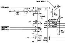
That doesn't really say anything. For example, in IBM XT the F/C pin is tied "low" through an inverter gate. It is quite possible that a 74LS27 gate is used to produce a constant logic "high" or "low"...
1695848170021.png

Clearly 14.31818MHz aren’t getting generated (not sure why) and I am not getting anything significant over on EFI. I guess that means the switching circuit is out of order?
The glitch free clock switching circuit requires both input clocks to be running. If one of them stopped, the switching circuit might not function properly...
So, I would investigate why 14.31818 MHz clock is not being generated first.
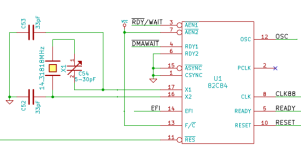
It appears that your board is using 82C84. Please note that the oscillator circuit for the original (supposedly TTL-LS) 8284 and CMOS 82C84 are different.
You can't simply switch these ICs, without modifying the clock circuit. Particularly, 82C84 needs load capacitors connected between the crystal pins and the ground, while 8284 has two 510 ohm resistors there instead.
Refer to the IBM XT schematic above for the 8284 crystal connection.
Here is the schematic for the 82C84:
1695848813451.png


CLK is 8MHz. PCLK is 4MHz. EFI looks weird? Maybe it’s because the 24MHz oscillator is too high for my LA?
The CLK and PCLK look good for a 24 MHz crystal. It is quite possible that your LA cannot sample 24 MHz frequency
 
Some of the caps beep for a very short while when putting the probes on them in continuity mode, others don’t. On my working board none of the caps exhibit this behaviour.
There are considerations required when measuring components in-circuit. When you have the leads on a particular component, you are actually measuring more than one component. In various scenarios, you need to allow for that. An example is shown at [here].

Note that continuity mode is not a short circuit detector. It is a low-ohms detector. More about that at [here].

Regaring 'beeps for a short while in continuity mode'. This is not unexpected. If I grab one of my IBM 5150 motherboards, and (disconnected from PSU) measure the resistance of the +5V/-5V/+12V/-12V lines, quite often I will initially see a low resistance on my meter, which rises whilst the capacitance on the line charges. Research capacitor theory if you are more interested in that.

As for why one motherboard showed the behaviour, and the other not. Possibilities that I can think of:
1. The two boards are not truly identical.
2. One (or both) not measured on their own (attached was a keyboard, or ISA cards, etc.)
 
EDIT2: By removing the 74LS27, F/C starts always high. Maybe there is a pull-up somewhere?
Disconnected TTL inputs are usually interpreted by the chip as HIGH. See [here] for some technical discussion on the subject.

... READY high (can’t remember if good),
Good.

OSC is mainly low, with some glitching to high every now and then. Nothing shows on screen.
Your CGA card probably requires the 14.318 MHz as a clock source.
 
Just to reiterate the importance of the 14.31818 MHz clock source.
Even if the CPU is getting the "turbo" 8 MHz clock, there are other things that will not work if 14.31818 MHz / OSC clock is not working. Most likely the system will not even boot.
  • The 8253 PIT uses OSC/12 clock. Without the clock, DRAM refresh will not work. The speaker will not work, unless programming it directly using 0x61 port. Timekeeping will not work. And as I said, it is likely that BIOS POST will fail pretty early on, while testing the PIT.
  • The original IBM CGA controller, and many 3rd party CGA cards rely on 14.31818 MHz being present on the OSC signal on ISA bus
  • The glitch free clock switching might not work properly if both input clocks are not running. This might be the reason for your observations of something seeing 8 MHz CLK and sometimes not seeing it.
 
Sergey, it depends. On the first "cheap" turbo boards, the peripheral chip clocks were taken from PCLK, with "interesting" results. The time of day clock ran too fast, the "beep" pitches from the speaker were too high and the ISA bus was run too fast.
 
It appears that your board is using 82C84. Please note that the oscillator circuit for the original (supposedly TTL-LS) 8284 and CMOS 82C84 are different.
You can't simply switch these ICs, without modifying the clock circuit. Particularly, 82C84 needs load capacitors connected between the crystal pins and the ground, while 8284 has two 510 ohm resistors there instead.
Refer to the IBM XT schematic above for the 8284 crystal connection.
Here is the schematic for the 82C84:
View attachment 1264898


The CLK and PCLK look good for a 24 MHz crystal. It is quite possible that your LA cannot sample 24 MHz frequency
Ding ding ding! You won! That was it - the board now lives again. The original 8284 was an M5L8284AP, and it actually had two resistors - while my non-working board had two 22pF caps. Swapped them around and et voilà! The board lives again!

The M5L8284AP generated OSC but didn't put out any CLK and PCLK, so it was definitely borked.

Now I am getting a RAM error, and it seems it always happens at 0KB. Chips are known good from my other board. Sometimes the error has alternating banks (0,2,4,6), (0,1,3,4,6,7), other times it reports every bank except parity as faulty. One time it did manage to go further and test the rest of the RAM. The error address changes every time.

What could be causing this?

Thanks again for your invaluable help!
 
Last edited:
Ding ding ding! You won! That was it - the board now lives again.
Excellent pick-up by sergey. Damn. I was hoping for the points. They would have put me over the threshold that entitles me to a 'I luv VCFF' T-shirt. :)

Now I am getting a RAM error, and it seems it always happens at 0KB. Chips are known good from my other board. Sometimes the error has alternating banks (0,2,4,6), (0,1,3,4,6,7), other times it reports every bank except parity as faulty.
You need to get the terminology correct. Banks and bits, per the IBM 5150 diagram at [here].

Sometimes the error has alternating banks (0,2,4,6), (0,1,3,4,6,7), other times it reports every bank except parity as faulty
Regarding the alternating bit failure. Typically, when a RAM address is tested, various test values are used against the address.

Following are four common values that are used:
00 hex (00000000)
FF hex (11111111)
AA hex (10101010)
55 hex (01010101)

Different BIOS' (and diagnostic software) may test in a different order to above, and may use additional test values.

What is common is that the test of an address is aborted as soon as there is a failure.
Example:
Address 00000, test #1 of 4: Write = 00, read-back = 00 <---- good
Address 00000, test #2 of 4: Write = FF, read-back = FF <---- good
Address 00000, test #3 of 4: Write = AA, read-back = FF <---- FAIL - ABORT - AA XOR FF = 55 (01010101) = bad bits 0,2,4,6

Above, "bad bits 0,2,4,6" does not mean that bits 1,3,5,7 passed.

Rudd's Diagnostic ROM does not abort mid way through testing an address. It uses all test values, and reports the combined results. So if remove all chips from bank 2 on a good motherboard, Rudd's Diagnostic ROM will report all bits in error (except for the parity bit).
 
Now I am getting a RAM error, and it seems it always happens at 0KB.
The error address changes every time.
Those two statements conflict, because 0 KB = address 00000.
But from my reading of post #28, the problem appears to be intermittent read/write of RAM.

All kinds of possibilities. Do you own a logic probe? Have the oscilloscope yet? Can you program EPROM's for the motherboard?
 
You need to get the terminology correct. Banks and bits, per the IBM 5150 diagram at [here].

Rudd's Diagnostic ROM does not abort mid way through testing an address. It uses all test values, and reports the combined results. So if remove all chips from bank 2 on a good motherboard, Rudd's Diagnostic ROM will report all bits in error (except for the parity bit).
Thanks for the enlightening link. I have been using your version of Ruud's Diagnostic ROM all along - right now on a cold boot it detected 640KB of RAM and it hung at "Testing RAM - Data ... 9". After rebooting I have got a "CRITICAL ERROR!" and a FAILED on "Check first 2 KB of RAM".

After a warm boot I now get the familiar

7 6 5 4 3 2 1 0 P
X X X X X X X X 0

Failure at address: 0 KB (exactly 00000)

I have also got an "Unexpected NMI" once.

EDIT: SuperSoft / Landmark's reports Interrupt Level 0 and the KBC as FAILED but the rest tests fine. RAM tested OK. Afterwards it kept freezing on “Keyboard Scan Lines” so I couldn’t test it further.

EDIT2: while looking for “interrupt level 0” on Google I have found my older thread on here, which never got any reply: https://forum.vcfed.org/index.php?t...errupt-level-0-and-keyboard-controller.75140/

EDIT3: RAM tests fine with Phatcode’s Super PC / Turbo XT ROM as well, but DOS hangs when booting.

Those two statements conflict, because 0 KB = address 00000.
But from my reading of post #28, the problem appears to be intermittent read/write of RAM.

All kinds of possibilities. Do you own a logic probe? Have the oscilloscope yet? Can you program EPROM's for the motherboard?

Well, it says 0 KB but the address varies slightly - 0000D, 00005, and so forth. Most of the times it fails at 00000. Now it’s failing around 32KB. Obviously nothing has been moved on the board.
Right now I have got the tested and working Bank 0 and Bank 1 from my other board in.

I have a logic probe, the aforementioned Saleae Logic 8 clone and a TL866CS along with a TL866II, with spare 2764s and 27128s to burn.

The oscilloscope won't be delivered until another 10 days or so.
 
Last edited:
Well, it says 0 KB but the address varies slightly - 0000D, 00005, and so forth. Most of the times it fails at 00000. Now it’s failing around 32KB. Obviously nothing has been moved on the board.
Ruud's Diagnostic ROM. That explains it. I had been thinking about enhancing the KB portion, e.g. 0 KB, 0.1 KB, 0.6 KB, 14.9 KB. '0 KB' would only be displayed if the address is 00000.

Thanks for the enlightening link. I have been using your version of Ruud's Diagnostic ROM all along - right now on a cold boot it detected 640KB of RAM and it hung at "Testing RAM - Data ... 9". After rebooting I have got a "CRITICAL ERROR!" and a FAILED on "Check first 2 KB of RAM".

After a warm boot I now get the familiar

7 6 5 4 3 2 1 0 P
X X X X X X X X 0
An intermittent problem in the RAM subsystem ?

* Intermittent loss of RAS ?
* Intermittent loss of CAS ?
* Intermittent loss of WE (intermittent writes) ?
* Intermittent addressing problem (e.g. write to address 00005, but the read-back of data actually hits a different address) ?

... and it hung at "Testing RAM - Data ...
If the problem is confined to the RAM subsystem, I do not expect any 'hanging'. Why? Ruud's Diagnostic ROM (as it is now) runs from ROM, and has the stack and variables in the unused portion of MDA/CGA video RAM.

I have also got an "Unexpected NMI" once.
Interesting.

A lot of the execution time of Ruud's Diagnostic ROM is spent testing RAM. Because of that, if there is an intermittent problem that 'hangs' the motherboard, one could get the impression that the problem is RAM related.

Are you sometimes seeing a hang during non-RAM related tests ?
 
EDIT: SuperSoft / Landmark's reports Interrupt Level 0 and the KBC as FAILED but the rest tests fine. RAM tested OK. Afterwards it kept freezing on “Keyboard Scan Lines” so I couldn’t test it further.

EDIT2: while looking for “interrupt level 0” on Google I have found my older thread on here, which never got any reply: https://forum.vcfed.org/index.php?t...errupt-level-0-and-keyboard-controller.75140/
Keep in mind that there may be multiple problems.

The Keyboard Controller' test in the Supersoft/Landmark diagnostic, is named 'Keyboard responds to reset' in recent versions of Ruud's Diagnostic ROM.
The 'Keyboard scan lines' test in the Supersoft/Landmark diagnostic, is named 'Keyboard stuck key' in recent versions of Ruud's Diagnostic ROM.
Both are explained at [here].
In recent versions of Ruud's Diagnostic ROM, the 'Keyboard stuck key' is not executed if the 'Keyboard responds to reset' test fails - there is no point.

EDIT2: while looking for “interrupt level 0” on Google I have found my older thread on here, which never got any reply: https://forum.vcfed.org/index.php?t...errupt-level-0-and-keyboard-controller.75140/
The 'Interrupt level 0' test in the Supersoft/Landmark diagnostic, is named 'Checking interrupt IRQ0' in recent versions of Ruud's Diagnostic ROM.
See 'Checking interrupt IRQ0' at [here].

Note that the test requires functional motherboard RAM, because low RAM is where the address vector is stored for the CPU interrupt that IRQ0 triggers.
If at the time of execution, that vector is incorrectly read, a hang would probably result.
 
7 6 5 4 3 2 1 0 P
X X X X X X X X 0
By the way. The parity bit showing as '0' is normal if there are any bad data bits showing.

When testing RAM on a motherboard, a reported RAM parity error could be due to either:
1. The parity generation/checking circuitry simply doing its job; or
2. Faulty parity generation/checking circuitry; or
3. Faulty RAM chip for parity.

Because of the possibility of #1, Ruud's Diagnostic ROM uses the logic of:

If during a RAM test, a parity error is indicated, the parity chip in the bank may or may not be faulty.
- If the test value read back differs to what was written, ignore the parity error.
- If the test value read back is the same to what was written, and a parity error indicated, that indicates a faulty parity chip (or parity circuitry).
 
Are you sometimes seeing a hang during non-RAM related tests ?
The answer will help direct investigative effort.

As I mentioned before, the 'Checking interrupt IRQ0' test is expected to hang the system if there is a bad read of the corresponding CPU interrupt vector stored in low RAM.
 
Ruud's Diagnostic ROM. That explains it. I had been thinking about enhancing the KB portion, e.g. 0 KB, 0.1 KB, 0.6 KB, 14.9 KB. '0 KB' would only be displayed if the address is 00000.


An intermittent problem in the RAM subsystem ?

* Intermittent loss of RAS ?
* Intermittent loss of CAS ?
* Intermittent loss of WE (intermittent writes) ?
* Intermittent addressing problem (e.g. write to address 00005, but the read-back of data actually hits a different address) ?


If the problem is confined to the RAM subsystem, I do not expect any 'hanging'. Why? Ruud's Diagnostic ROM (as it is now) runs from ROM, and has the stack and variables in the unused portion of MDA/CGA video RAM.


Interesting.

A lot of the execution time of Ruud's Diagnostic ROM is spent testing RAM. Because of that, if there is an intermittent problem that 'hangs' the motherboard, one could get the impression that the problem is RAM related.

Are you sometimes seeing a hang during non-RAM related tests ?

I have switched to a V20 I had lying around and the system got a lot stabler. No NMI issues anymore.

After reseating most RAM ICs, I now can complete the DATA test successfully 100% of the time, but it fails on Address, most of the time in the 0-192KB area.

I think there is a thermal component in this issue as slapping an huge fan over the RAM part of the mobo lets Ruud's Diagrom complete 4-5 passes with no issues.

One thing is unclear to me - bank 0 does the first 256KB of RAM - but which chip does for example the first 32KB in Bank 0? 7 or 0?

It's not hanging anymore on anything, except the RAM tests. KBC keeps failing but the keyboard worked in DOS 3.1, so it's probably my Model M doing something weird.

The answer will help direct investigative effort.

As I mentioned before, the 'Checking interrupt IRQ0' test is expected to hang the system if there is a bad read of the corresponding CPU interrupt vector stored in low RAM.
This still happens, but I will keep looking into it after fixing this RAM issue. If it has something to do with low RAM, it might be the same issue altogether.

EDIT: I think I have found the issue - placing a fan over the 8253 and 8259 made the issue go away. I gave these two ICs a good cleaning and I am now testing again just to make sure that everything works.

Now the only "issue" remaining is the "Checking interrupt IRQ0"...

EDIT2: Spoke too soon, the issue came back... Will update later.
 
Last edited:
One thing is unclear to me - bank 0 does the first 256KB of RAM - but which chip does for example the first 32KB in Bank 0? 7 or 0?
These chips store bits, not bytes. So 8 chips are required to store bytes. And the ninth chip stores the parity bit.
 
These chips store bits, not bytes. So 8 chips are required to store bytes. And the ninth chip stores the parity bit.
Does this mean that the first 0-32Kb addresses are parallelised over the 9 chip's A0?
Regarding the remaining issues. Are they present if the board starts in non-turbo mode?
The board is rock solid when working in 4.77MHz mode. The IRQ0 error is still there, though.

As soon as I "turbo" the Data/Address errors in the 0KB-256KB of RAM come back.

Maybe one of the buffers not being able to tolerate the faster speeds?

Anyway the SuperSoft / Landmark ROM does not report the IRQ0 error nor reports memory errors but tells me about a bunch of parity problems.

It seems that putting the FDC in makes the problem worse... At least it looks like that.

BTW, slapping a fan over the 8253 and 8259 alleviates/solves the issues somehow.

EDIT: Not anymore. Everything is so randomic, this has been so frustrating compared to
the other issue I had. At least with the clock issue I knew there was something wrong somewhere, here it just starts working out of the blue only to stop working after a reboot.
 
Last edited:
Back
Top