• Please review our updated Terms and Rules here

Unidentified Turbo XT Clone has F/C stuck low

jbenam

Member
Joined
Nov 5, 2018
Messages
35
Location
Italy
Hello there,

I have this non-working XT turbo clone that isn’t booting - core chips are tested (on another XT board) and working.

I have tried replacing the 14MHz crystal but this being an XT turbo board I guess it does something funky with the keyboard to allow turbo using a combination of keys.

I can’t see a turbo jumper anywhere to force it to boot in 4.77MHz mode (which I guess it would do tying F/C to low to use the 14MHz crystal) so I guess that it boots in turbo mode.

Can I safely tie F/C to ground or do I risk damaging the turbo part of the circuit?

I have traced F/C going from the 8284 to pin 12 of the 74LS27 underneath the dip switches. Since it has only output it was easily traceable to pin 1 of one of the 74LS244 underneath, afterwards I wasn’t sure anymore of what to look for.

EFI instead goes from the 8284 to one of the 74LS244 below, on pin 7.

What else could I be looking for with just a multimeter? Ruud’s diagrom shows nothing with a known-working CGA card.

I haven’t got an oscilloscope (yet) but I am getting one soon. Still undecided on what to get since I work on a large array of retro systems and I haven’t got much in terms of budget. Heard good things of the DSO2512 but I was also looking at the DPOX180H.

Anyway, I haven’t been able to identify this board at all as it hasn’t got any markings expect that “Start” logo you can see on top of the 8255.

Thanks for helping!
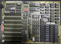
IMG_1672.jpeg
 
Hi

Have you tested all the RAM chips and verified they're good? I see that one is missing?

With a multimeter you can check if the CPU comes out of Reset. If it does your next things to look at are ROM and RAM. Also make sure the DIP switches are correct... XT boards won't boot if the RAM and video settings are not corresponding to what's on the board.

Regarding a scope: Better save up and get a good used one. You can also look into RIGOL's new DHO800 series, it looks very promising and for around 400€ you get a lot of features and 4 channels including probes. I have the older model DS1054Z, now that the new one is coming out it might be your chance to get it cheaper

PS: attach a speaker to hear if the board complains about something
Hello and thanks for your reply. I remember testing them all some years ago and IIRC they were fine. Anyway Ruud’s diagnostic ROM should test the RAM chips accurately and from what I gather even if there is a faulty RAM in a low enough address that shouldn’t block the CPU to come out of RESET.

Yeah, the CPU doesn’t come out of RESET since there is no clock at all coming out from the 8284 - that’s my issue at the moment. The 8284 is a known good and it comes from my other board.

DIP switches are okay and the same as my other board.

400EUR for an oscilloscope is totally out of my budget. I do repairs for my own stuff and during my free time - as such I can’t justify the investment. After reading a bunch of stuff I have settled on the DSO2512G. It only goes up to 37MHz or so which is plenty enough for most of my retro systems (except P1+ motherboards but you can’t have everything) :)

Nothing coming out of the speaker since there is no clock. BTW power good signal looks good and behaves as my other board. On my other board I can see X1 and X2 oscillating but not on this one, which is fine since F/C isn’t tied to low and as such it isn’t using the crystal.

I was just wondering if I could just tie F/C to low to see if I can get it to boot in 4.77MHz mode without wrecking anything.
 
You'll likely find that the F/C signal eventually makes its way to a pin on the 8255.
I guess so - since it must somehow reach through the keyboard matrix to allow switching turbo modes.

I really loathe the thought of having to test every 74 on the board, but they are socketed so it could’ve been worse I guess.

Do you advise trying tying F/C to GND on the 8284 just to see if the board works in 4.77Mhz?
 
I really loathe the thought of having to test every 74 on the board, but they are socketed so it could’ve been worse I guess.
Do you have a chip programmer or a breadboard and some parts to test 74 logic chips? If yes it would be good if you can verify them. Otherwise it's probably best to wait for the arrival of your scope
 
Do you have a chip programmer or a breadboard and some parts to test 74 logic chips? If yes it would be good if you can verify them. Otherwise it's probably best to wait for the arrival of your scope
Yep, I have a TL866II which can test most (but not all) of the 74s. For the rest I use my other board (which is entirely socketed as well).

Anyway lifting F/C and tying it to ground didn’t help, crystal still didn’t oscillate and reset is stuck high - I think the issue lies somewhere else, probably on AEN1 but I am still not 100% sure.

I have as such purchased one of those very cheap 8ch Logic Analysers and it should be with me tomorrow. I will record the 8284 on my working board and compare it with my broken turbo board. Will attach recordings here :)
 
XT boards won't boot if the RAM and video settings are not corresponding to what's on the board.
If I go to my IBM XT and clone XT motherboards, and adjust the two RAM switches, the computers still boot. All that changes is the amount of RAM that the POST counts up to.
 
Yeah, the CPU doesn’t come out of RESET since there is no clock at all coming out from the 8284 - that’s my issue at the moment. The 8284 is a known good and it comes from my other board.
This is fundamental, and so should be reasonably easy to trace to the cause, once you have a logic probe or oscilloscope.

On my other board I can see X1 and X2 oscillating but not on this one, which is fine since F/C isn’t tied to low and as such it isn’t using the crystal.
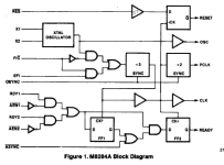
Although, if the block diagram (see below) in the 8284 datasheet is to be believed, F/C does not enable/disable the 'XTAL OSCILLATOR' in the diagram. Based on the block diagram, irrespective of the state of F/C, the XTAL OSCILLATOR should always be oscillating if there is an appropriate crystal attached to the X1 and X2 pins. And in regard to the OSC output pin, I am not seeing anything in the datasheet that indicates that there will be no output if F/C is HIGH.

1695597932628.png
 
Last edited:
Anyway lifting F/C and tying it to ground didn’t help, crystal still didn’t oscillate and reset is stuck high - I think the issue lies somewhere else, probably on AEN1 but I am still not 100% sure.
Are you saying the crystal on your board is not oscillating? Do you have a method to verify your crystal is working e.g. the "Hz" setting on your multimeter (measure from a crystal pin to its outer body)? If not you could have a problem with the crystal itself or the circuit forming the oscillator.

If I go to my IBM XT and clone XT motherboards, and adjust the two RAM switches, the computers still boot. All that changes is the amount of RAM that the POST counts up to.
Yeah you're right! Sorry about that.. I must have messed up something else on my board when I was trying the DIP switches (it was quite a while ago)
 
Hello there, sorry if it took a bit of time for me to reply but I didn’t have much time to tinker until tonight.

After rebooting loads of times, I could see 8MHz on CLK and 4MHz on PCLK, which confirms my hunch of the board booting in turbo mode by default. Unless it boots in 4.77MHz mode and I have somehow glitched it to boot in turbo mode for once? Not sure.

Sadly the board went back to not booting after this one time.

My LA can read X2 with no issues on my working board, but on this one the signal is stuck. Now that I think of it I should also actually put one probe on EFI, but I am not sure my LA can actually show 24MHz (it’s one of those cheapo Salaea clones, 24MHz unit). Will try that tomorrow.

Since it seems that both oscillators should be running at all times, I am definitely having an oscillator issue somewhere. I am sure that this one oscillator was a good part since I have tested it first on my other board but I will purchase some other crystals and will socket both boards for good measure to allow me to be sure that the oscillators are working using my one working board.

What could make this board temperamental when booting? Maybe one of the caps is busted? IIRC tantalum caps short when they’re bad.

If that’s right I should just be able to find one which beeps when my multimeter is set to continuity, is that correct?

Thanks again!
 
What could make this board temperamental when booting? Maybe one of the caps is busted? IIRC tantalum caps short when they’re bad.
If a capacitor that is filtering a voltage rail goes short-circuit, it will overload the power supply, resulting in the switch mode power supply shutting down.

( BTW: Tantalum caps also go open-circuit. )

I should also actually put one probe on EFI, but I am not sure my LA can actually show 24MHz (it’s one of those cheapo Salaea clones, 24MHz unit).
What is is expected to be shown in such a situation (inadequate sampling frequency) is something of a lessor frequency.

( Per [here], a 24 MHz sampling frequency doesn't even do 4.77 MHz justice. )
 
My LA can read X2 with no issues on my work board, but on this one it’s completely dead.
Regarding 'XTAL OSCILLATOR' in 8284:
X2 will have a analogue signal on it. I think one needs to be careful in making a decision based on an LA in digital mode. If that 'oscillator is an oscillating', your LA should show the oscillations on the 8284's OSC output pin.
 
What could make this board temperamental when booting?
Lots of things. But you have isolated the problem to a nil 'clock generation' cause. That rules out the vast majority of the motherboard circuitry.

And you need to keep an open mind. For example, multiple problems. For example, is it the case that sometimes at power-on, the F/C pin is HIGH (turbo) and sometimes it is LOW (non-turbo), plus clock generation for non-turbo mode isn't working.

If you are not seeing oscillations on the 8284's OSC output pin, work backwards: You have replaced the 8284 chip with a known-good one. You have replaced the 14.318 MHz crystal. But what exactly is the circuitry connected to the X1 and X2 pins. Is the X1/X2 circuitry as simple as that for the IBM XT (see [here]), or is it something else.

Is the +5V to the 8284, as measured on the Vcc pin of the 8284, always good ?
 
Regarding 'XTAL OSCILLATOR' in 8284:
X2 will have a analogue signal on it. I think one needs to be careful in making a decision based on an LA in digital mode. If that 'oscillator is an oscillating', your LA should show the oscillations on the 8284's OSC output pin.
It is a bad idea to measure frequency on the crystal itself or X1 and X2 pins. Your measurement equipment will introduce enough capacitance, impedance, and noise to screw up the clock oscillator.
Instead, measure the clock on the OSC output (pin 12).

Are you saying that F/C is tied high?
That is expected on most well designed Turbo XT boards. These boards use the following clock generation method:
1. The 8284 is used to generate 14.31818 MHz clock
2. An additional clock oscillator, say 24 MHz, is used to generate the "turbo clock"
3. There is a glitch-free clock switching circuit that selects one of the clocks above. The circuit is typically controlled by an unused Port B output of 8255, e.g. PB2.
4. The output of the clock switching circuit is connected to the EFI input of the 8284, while its F/C input is tied high, so that it uses the clock provided on the EFI input to generate CLK and PCLK signals
5. There might be additional logic that switches the board to the standard 4.77 MHz clock during DMA operations, and/or adds wait states for I/O and external memory when operating in turbo mode

(Cheap / early turbo XT boards might use F/C to switch between clocks. But that does not guarantee glitch-free switching, and might result in an unstable operation while switching the clock)
 
If a capacitor that is filtering a voltage rail goes short-circuit, it will overload the power supply, resulting in the switch mode power supply shutting down.

( BTW: Tantalum caps also go open-circuit. )


What is is expected to be shown in such a situation (inadequate sampling frequency) is something of a lessor frequency.

( Per [here], a 24 MHz sampling frequency doesn't even do 4.77 MHz justice. )
Voltages are fine, and I can only see a handful of tantalum caps near the 8282 and two next to the ISA slots.

Some of the caps beep for a very short while when putting the probes on them in continuity mode, others don’t. On my working board none of the caps exhibit this behaviour.

I also have one of those cheapo M-Tester clones based on that one open-source project that also works as an ESR Meter but I have never used it as such.

I know that an LA isn’t exactly the best instrument for analog signals but right now I haven’t got an oscilloscope yet :)

Regarding 'XTAL OSCILLATOR' in 8284:
X2 will have an analogue signal on it. I think one needs to be careful in making a decision based on an LA in digital mode. If that 'oscillator is an oscillating', your LA should show the oscillations on the 8284's OSC output pin.
It does show it as “oscillating” on my working board but on my non-working board it’s stuck low.

Lots of things. But you have isolated the problem to a nil 'clock generation' cause. That rules out the vast majority of the motherboard circuitry.

And you need to keep an open mind. For example, multiple problems. For example, is it the case that sometimes at power-on, the F/C pin is HIGH (turbo) and sometimes it is LOW (non-turbo), plus clock generation for non-turbo mode isn't working.

If you are not seeing oscillations on the 8284's OSC output pin, work backwards: You have replaced the 8284 chip with a known-good one. You have replaced the 14.318 MHz crystal. But what exactly is the circuitry connected to the X1 and X2 pins. Is the X1/X2 circuitry as simple as that for the IBM XT (see [here]), or is it something else.

Is the +5V to the 8284, as measured on the Vcc pin of the 8284, always good ?

Just checked, F/C is stuck LOW at all times. As I have speculated earlier, after so many reboots I must have glitched it in HIGH and I could see 8MHz over on OSC.

I have checked everything with a multimeter and X1/X2 are connected exactly the same as my other board (which is the same as IBM’s XT). Maybe the crystal wasn’t working after all? Not sure. Need to some spares to keep at hand. 8284 gets a steady 4.8V at all times.

It is a bad idea to measure frequency on the crystal itself or X1 and X2 pins. Your measurement equipment will introduce enough capacitance, impedance, and noise to screw up the clock oscillator.
Instead, measure the clock on the OSC output (pin 12).

Are you saying that F/C is tied high?
That is expected on most well designed Turbo XT boards. These boards use the following clock generation method:
1. The 8284 is used to generate 14.31818 MHz clock
2. An additional clock oscillator, say 24 MHz, is used to generate the "turbo clock"
3. There is a glitch-free clock switching circuit that selects one of the clocks above. The circuit is typically controlled by an unused Port B output of 8255, e.g. PB2.
4. The output of the clock switching circuit is connected to the EFI input of the 8284, while its F/C input is tied high, so that it uses the clock provided on the EFI input to generate CLK and PCLK signals
5. There might be additional logic that switches the board to the standard 4.77 MHz clock during DMA operations, and/or adds wait states for I/O and external memory when operating in turbo mode

(Cheap / early turbo XT boards might use F/C to switch between clocks. But that does not guarantee glitch-free switching, and might result in an unstable operation while switching the clock)
Yep, noticed as much. My CGA card stops display an image if I do so. I am using OSC now.

F/C is stuck low. EFI has some weird glitching going on, PCLK is stuck high while CLK starts low then gets stuck high.

Clearly 14.31818MHz aren’t getting generated (not sure why) and I am not getting anything significant over on EFI. I guess that means the switching circuit is out of order?

Sadly I don’t have schematics for the switching circuit so I am a bit lost here.

Thank you both for your precious help!

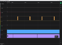
EDIT: Managed to glitch again F/C as high, this is what I am getting:

Capture2.PNG

CLK is 8MHz. PCLK is 4MHz. EFI looks weird? Maybe it’s because the 24MHz oscillator is too high for my LA?

EDIT2: By removing the 74LS27, F/C starts always high. Maybe there is a pull-up somewhere? Anyway. I get RESET high then low (good), READY high (can’t remember if good), PCLK oscillating at 4MHz and CLK oscillating at 8MHz. OSC is mainly low, with some glitching to high every now and then. Nothing shows on screen.
 
Last edited:
Back
Top