• Please review our updated Terms and Rules here

US electrical supply question

roberttx

Veteran Member
Joined
Aug 6, 2015
Messages
1,133
Location
Texas
A friend of mine has bought a diner and the city want her to replace the outlets in the kitchen with ones that incorporate a GFCI. The inspector said something along the lines of if the ground is wired correctly then she would only need to fit them to the first one.

I'm more familiar with the UK system of ring mains, RCDs, etc but, AAUI, the US uses radial circuits. I've checked the outlets and verified that they are correctly grounded. My proposed next step is to use a device that I have that injects an RF signal into a circuit, by plugging into an outlet. It turns the wires into an antenna and you then move a basic signal tracer over the wall to map the position of the wires.

I hope that, in this way, I'll be able to identify how many radial circuits there are and which outlets are on which. Presumably the "first one" would be the one closest to the breakers?

Does this sound right to y'all? Am I missing anything?
 
Presumably the "first one" would be the one closest to the breakers?

Yes, and sometimes this leads to some oddities, like the outlets on one side of my house being controlled by an obscure GFCI in a bathroom on the opposite side of the house. (I used a signal tracer to find this out; I was convinced there was a break in the wiring somewhere; didn't realize there was a tripped GFCI)
 
It varies from state to state, but here southeast Michigan, per code, you need a ground interrupt if the electrical outlet is within 6 feet of any water source. Daisy-chaining is acceptable.
 
I was torn between GFCI breakers in the distribution panels and GFCI outlets. I opted for GFCI outlets, reasoning that resetting the interrupter would be easier for someone not comfortable with breaker panels. Most recent GFCI outlets also have illuminated indicators, so finding a tripped one is easy.

However, I did incorporate surge suppression into my panel, since there's nothing to reset.

Code can be a bit hard to interpret with requirements for GFCIs. Generally, outlets where water and temporary-use outlets are present ground-fault protection is required, so kitchens, bathrooms, laundry rooms and outdoor outlets--and sometimes garage outlets. However, I discovered a notable exception when wiring the outlet for my septic tank effluent lift station--install a single outlet receptacle with the pump plugged in permanently and the GFCI isn't required, as it's viewed as a "permanent" installation. Make the outlet a duplex one and you have to use a GFCI. At least that's what the local building inspector says.
 
... then she would only need to fit them to the first one.
In other words, the other outlets are daisy-chained off the outlet where the GFCI is installed, since terminals are provided for that. If all outlets go back to the panel on individual wires then it may be more practical to install GFCIs on every outlet, or use a breaker. Outlet GFCIs are as cheap as chips in the US and then it's easy to test or reset them.
 
Thanks guys. It's good to know that I wasn't way off base.

I've since been on site and pulled a couple of the covers. There are at least two circuits there: the original wiring (2 wire, grounded neutral) and one that was added later (3 wire, 2 hots and a common neutral, with protective ground).

I will, of course, have to inspect the breaker box to determine whether the 3 wire circuit was installed correctly, with a multi pole breaker or whether they cut corners and used two single pole breakers.

Then, I think I'm going to have to pull all the covers and audit the number and types of circuit. Depending upon what I find, it may be more cost effective to go with GFCI breakers.
 
I've since been on site and pulled a couple of the covers. There are at least two circuits there: the original wiring (2 wire, grounded neutral) and one that was added later (3 wire, 2 hots and a common neutral, with protective ground).

Are both romex wires available in a single wall box? If so, both were run at the same time because you'd have to tear the walls completely apart to pull another romex run. If they're in different boxes, they'd still be done at the same time, unless all of the wall boxes are external to the wall with conduit running to them.

Depending upon what I find, it may be more cost effective to go with GFCI breakers.

While a GFCI breaker would be more cost effective, it would be a potential pain in the ass later.

Just think of the nightmare scenario. You have a wet and greasy kitchen with lots of appliances, and one decides that it's been insulted one too many times and starts leaking current to trip the GFCI. Now it takes out the whole circuit where you have lots of things plugged into, some may be in incredibly difficult spots to reach. So you're forced to shut the whole kitchen down to chase a ground fault, which may take hours and end up as time wasted because the appliance may suddenly stop leaking current after a breaker reset. I've had restaurant customers who have had to chase ground fault problems for months to figure out what the issue was.

I would recommend using GFCI plugs in every outlet wired in parallel (vs. the normal series wiring.) GFCIs wired in parallel would mean that one plug could trip independently of the others and not take everything down. Then you'd know exactly which appliance had the ground leak and quickly rectify the problem.

So you have the choice of spending more now, or a lot more down the line chasing ground faults.
 
It would seem to be a better choice to install a GFCI breaker in the breaker panel instead of a single outlet. Then every outlet on that circuit is protected.

With most GFCI outlets, if it's the first in the circuit, all other outlets will be protected. But for a retrofit, the GFCI breaker is an easier install since you don't need to determine which outlet is the first.

I would recommend using GFCI plugs in every outlet wired in parallel (vs. the normal series wiring.) GFCIs wired in parallel would mean that one plug could trip independently of the others and not take everything down. Then you'd know exactly which appliance had the ground leak and quickly rectify the problem.

No outlets in the US should be wired in series. What you are describing is daisy chain vs. home run wiring.
 
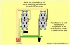
I did a little bit more examination, yesterday. The three wire circuit terminates at two double outlets in a single wall box. Each has a different hot and they share a common neutral, delivering 115V at each outlet. The breaker box end is messed up. One hot is on one half of a "2-in-one" breaker, the other is on one half of a different "2-in-1" breaker. I think I should pull some breakers and swap some wires around and just not tell anybody that I did so.

AFAICT, every outlet is on a different breaker. I've located two breaker boxes, so far and mapped most of the outlets to breakers. Except, there are a couple that don't seem to be able to be switched off by any breaker in either box. So, either there's a third box that I have yet to locate, or I'm missing something. Maybe my signal tracer deal will help with that.

I still have to crack all the outlets and see what's inside. The city wants GFCI on the infrastructure, not the appliances, so GFCI plugs won't cut it. But I am leaning back towards GFCI outlets rather than GFCI breakers.
 
Last edited:
I'll have to read code, but two hots with one neutral return (unless that neutral is of a heavier gauge) probably violates code, as the return is not rated for carrying the same current as the two hot conductors combined. The 4-wire setup is usually used when you have an appliance whose main load is 240V, but may also have some smaller 120V demands. Some kitchen ranges were constructed like this, with the clock or other electronics running from 120V, while the burners ran from 240V.

4 wire setups are also used for delta-fed 3-phase situations, which I doubt applies here.

The setup sounds like a nightmare.
 
Shared neutral is allowed most places if the hots are on different phases. In that configuration, the combined neutral return current will never be more than the current of one hot. If both outlets are loaded the same, the return current is actually zero, because the phases cancel.
 
Actually I believe this is an accepted practice (as long as both hot wires are from opposite sides of neutral) but are no acceptable with GFI outlets which require separate neutral runs.

wiring-double-outlet.jpg

I'll have to read code, but two hots with one neutral return (unless that neutral is of a heavier gauge) probably violates code, as the return is not rated for carrying the same current as the two hot conductors combined.
 
Actually I believe this is an accepted practice (as long as both hot wires are from opposite sides of neutral) but are no acceptable with GFI outlets which require separate neutral runs.

View attachment 44803

I'll have to look into that part about GFI outlets needing separate neutral runs. That might be problematic.

I solved the mystery ot the missing breaker box - there isn't one. Turns out my helper, yesterday, wasn't paying attention as I was flipping breakers. I now have all of the outlets mapped to breakers.
 
Actually I believe this is an accepted practice (as long as both hot wires are from opposite sides of neutral) but are no acceptable with GFI outlets which require separate neutral runs.

View attachment 44803

If the hot wires are used as the circuit (i.e. a 240V supply, like my table saw), yes, it's perfectly legit--you don't even have to have a neutral--just a ground wire:

240receptacle.jpg


But if you're using the supply for two 120V circuits, then it's not code. Consider that using the distribution in this manner would enable connection of two full loads using the current-carrying capacity of the wire on each of the hots, but running twice the current through the neutral.

As I said before, the only exception that I can think of is the situation where a smaller secondary load, such as a clock or electronics requires 120VAC. Since the primary load is across the two hot wires, this doesn't exceed the rated current-carrying capacity of the neutral. You often see this situation in the case of some permanently-wired kitchen appliances.

I'm a bit of a stickler for code. For example, a 20A 120V circuit that feeds a single 20A receptacle should have the appropriate 20A-rated receptacle:

5352-W.jpg
 
Last edited:
But if you're using the supply for two 120V circuits, then it's not code.

I thought multiwire branch / split receptacle circuits were code? As plasma points out, the two mains must be on different phases.

Regardless, I'm glad I don't have any of the things in my home (at least not that I'm aware of). It seems to me if you were ever to lose the neutral, really bad things could happen. I was in a restaurant when they lost a neutral to a subpanel -- lights burned out, appliances started smoking, and we evacuated as the dining area filled with noxious fumes.

ETA: An article where someone did the math to show what might happen to a TV and a hairdryer plugged into a multiwire branch circuit if the shared neutral becomes open: http://www.ecmweb.com/content/multiwire-branch-circuits-can-be-dangerous
 
Last edited:
I thought multiwire branch / split receptacle circuits were code? As plasma points out, the two mains must be on different phases.

Agree, and I believe code requires a double pole breaker to make sure both legs are shut off at the same time (and on opposite phases).
 
There's little wrong with a split-feed multiwire branch, so long as the common return is rated for the combined load current, which is the point I've been trying to make. Clearly two 20A circuits with a single 14AWG neutral return doesn't meed that requirement--the return could be called on to carry 40A. And yes, there's a definite danger if the common return becomes open between the panel and the receptacles.

Even if the local electrical inspector passes it (which I doubt), it's lousy practice--and potentially dangerous.

FWIW, the only 240V GFCI setups that I've seen have been GFCI breaker sets installed in the distribution panel. I don't think that I've ever seen a 240V GFCI outlet.
 
Last edited:
Clearly two 20A circuits with a single 14AWG neutral return doesn't meed that requirement--the return could be called on to carry 40A..

Not if the two hots are on different phases. If they were both run at full capacity, the neutral current would be zero.

This means, of course, that I will have to look carefully at where the 3 wire hots originate in the breaker box.

On the matter of GFCI receptacles with a shared neutral, it appears that it's OK to share the neutral on the line side, just not on the load side. As they are all on separate circuits, with no outlets spurred of of other oultets, it seems that I should be able to get away with that.

FWIW, the only 240V GFCI setups that I've seen have been GFCI breaker sets installed in the distribution panel. I don't think that I've ever seen a 240V GFCI outlet.

This could be tricky. Fortunately, the only 240V outlet that I have to deal with is on the more modern of the two breaker boxes, so a GFCI breaker should be readily available.
 
Back
Top