miata
Experienced Member
Hi Vectrex experts,
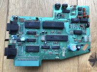
i found another Vectrex but unfortunately it is not happy Similar to my other one (before Daver2 helped me to fix it) I can hear the gameplay but there are no vectors on the screen. I can see the neck of the tube glowing so I still have some hope to fix it. I did the first checks on my own as Dave has teached me ( thanks again, Dave):
- Power from the transformer is at 10,5 VAC on both lines, ok
- I can measure +5VDC, -5VDC, -13VDC at the analog and digital board in a good range
- I also find the supply voltages on the various chips at the digital board, they look ok too
- I replaced already IC207, IC301, 302 and 303 taken from my other Vectrex- obviously no issue here
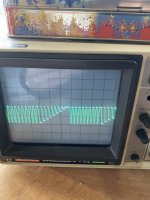
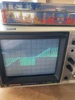
- I used my scope to look to the X,Y and Z waveforms and they look all good on both boards and according the manual
However I found these issues:
1. I checked the voltages at the CRT PCB and they look ok apart from EP505, here I measure -9,25VDC which looks off
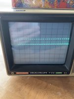
2. At IC302-14 I get a flatline with my scope instead of a waveform
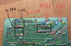
3. Very strange are the voltages on both Pots R333 and R335, I measure -5VDC on all 3 pins on each Pot independent what is the position of adjustment. Actually and according to my other Vectrex there should be +5VDC on one side and -5VDC on the other and then with the pot the voltage will be adjusted I assume. Something is not right here!
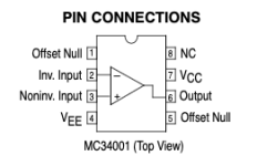
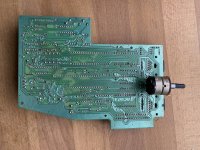
I decided to follow up the last issue first and de- installed the digital board. Looks like that all 3 Pins on R333 and R335 are connected to IC 304 or IC306. Maybe one of these chips or even both are faulty?
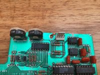
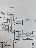
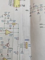
Unfortunately my schematic does not fit to my hardware although it says its for Revision 3GE like on the sticker on my digital board. There is no IC306 in my schematic but on the board A bit difficult to check what is going on here.
Is there anybody able to help me?
thanks
best regards
Denis
i found another Vectrex but unfortunately it is not happy
- Power from the transformer is at 10,5 VAC on both lines, ok
- I can measure +5VDC, -5VDC, -13VDC at the analog and digital board in a good range
- I also find the supply voltages on the various chips at the digital board, they look ok too
- I replaced already IC207, IC301, 302 and 303 taken from my other Vectrex- obviously no issue here
- I used my scope to look to the X,Y and Z waveforms and they look all good on both boards and according the manual
However I found these issues:
1. I checked the voltages at the CRT PCB and they look ok apart from EP505, here I measure -9,25VDC which looks off
2. At IC302-14 I get a flatline with my scope instead of a waveform
3. Very strange are the voltages on both Pots R333 and R335, I measure -5VDC on all 3 pins on each Pot independent what is the position of adjustment. Actually and according to my other Vectrex there should be +5VDC on one side and -5VDC on the other and then with the pot the voltage will be adjusted I assume. Something is not right here!
I decided to follow up the last issue first and de- installed the digital board. Looks like that all 3 Pins on R333 and R335 are connected to IC 304 or IC306. Maybe one of these chips or even both are faulty?
Unfortunately my schematic does not fit to my hardware although it says its for Revision 3GE like on the sticker on my digital board. There is no IC306 in my schematic but on the board
Is there anybody able to help me?
thanks
best regards
Denis
Attachments
Last edited:

