• Please review our updated Terms and Rules here

VECTREX WITH PROBLEMS

The next thing to do (now you have the diagnostic cartridge) is to follow the X signal from the logic board through the monitor circuitry.
Thanks so much!
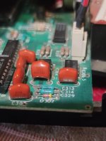
Ok, so i do i have to follow the signal from connector J301 going backwards?
 
J301 going forwards to J402 on the power board and then through the power board.

The signal should ‘look’ similar to that on the logic board, but it may be at a different amplitude.

I would also compare and contrast the signal output on the Y side of the logic board to the same point as you are measuring the X signal on the power board. The two sides (X and Y) are identical, so if you measure a peak-to-peak voltage of 0.5 Volts on the X side, but you see 1.5 Volts peak-to-peak on the Y side at the same point, something is wrong!

Does this make sense?

Dave
 
I also saw this capacitor on logic board....looks broken right?

I changed with a new one but i have always same problem :(
 

Attachments

  • Schermata 2022-03-06 alle 11.41.45.jpg
    Schermata 2022-03-06 alle 11.41.45.jpg
    99.6 KB · Views: 9
Last edited:
Looks can be deceiving...

That video is really interesting. It should be a cross-hatch of course...

The Y deflection seems to be fully there, but not the X. Interestingly, the picture ‘starts’ in the middle and deflects to the right; but not to the left. All the Y lines appear as mush...

I am not sure myself now whether the problem is the analogue section of the logic board, the power board, or a mixture of the two.

With the strangely formed lines, I am thinking integrators...

Let me have a think. Do you have a dual variable dc voltage generator at all?

We could also do with @Hugo Holden with his vast analogue knowledge helping out a bit.

Dave
 
Yes. The integrator capacitors are C312 and C313 (0.01 uF) on the logic board.

But these aren’t components from your ‘bits box’. They are +/- 5% tolerance polystyrene capacitors.

Dave
 
A polyester capacitor is a ‘normal’ capacitor.

But general capacitors usually have a +/- 20% tolerance, and are, therefore, no good for this application. This circuit should be a highly accurate integrator.

You must purchase the specific parts identified in the bill of materials of the service manual.

Dave
Ok, but this is the next step that i must doing or not? Thanks!
 
Right.

On the power board there should be two (2) potentiometers:

R401 - XSIZE.
R408 - YSIZE.

Can you find these two (2) potentiometers?

If so, make a note of where they are currently set to.

Display the cross-hatch image of the diagnostic cartridge on the screen.

Rotate R401 (XSIZE) first one way and then the other and finally put it back where it was before you started twiddling. As you twiddle the potentiometer, note the image displayed on the screen.

The width of the displayed image should shrink and expand as you twiddle the potentiometer first one way and then the other.

Ditto for R408 (YSIZE); but this time the height of the displayed image should shrink and expand as you twiddle the potentiometer first one way and then the other.

If you can’t find the potentiometers, report back. They may not be marked. The Vectrex service manual may give you a clue as to where to find them.

Dave

Thank you! I'll do this tomorrow because I'll be out tonight, I'll update you tomorrow on the result! Have a good evening!
 
Hi Dave, I did what you asked me: if I turn the y-axis potentiometer I can see the image shrink towards the center,
if instead I turn the one of the X axis, I can see it shrink or widen from the right side to the center and from the center to the right side ... never anything on the left side :(
 
That’s OK I think.

The Y direction is both above and below the centre of the screen, so the HEIGHT control should work equally on the upper half of the screen and the lower half of the screen.

I suspect the X direction is working from the centre to the right only, So the WIDTH control will only work on the right half of the screen.

I am going out tonight, so we will pick-up on this repair tomorrow.

I am getting annoyed with this machine now, so the next thing is to make some voltage measurements with the oscilloscope. I will post where to measure for tomorrow.

Dave
Ok Daver, thanks so much ;)
Have a good evening and dinner :)
 
Back
Top