• Please review our updated Terms and Rules here

VIC-20 Power Regulator Modernization Experiment

CommodoreZ

Experienced Member
Joined
May 18, 2007
Messages
180
Location
Z Labs.
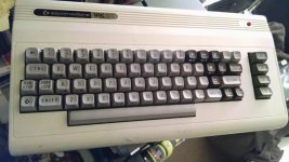
A few years ago, I acquired a pile of VIC-20s in various states of disrepair, some relegated to parts machines. Using chips harvested from dead 1541 drives, an NOS C16 keyboard, and a few other bits and pieces, I was able to build one functional VIC to add to my collection. A frankenVIC if you will.
c16med.jpg

One thing that always concerns me is running Rev E motherboards for too long, due to the heat they start to generate. A few months ago, I saw some project on hackaday (I think it was hackaday anyway) creating switching power regulators to drop right into TO-3 sockets. I forgot about it for awhile, but it came to mind again recently, and it dawned on me that a VIC-20 would be an ideal test case for such a device.

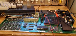
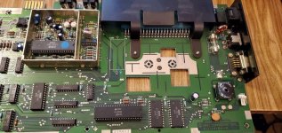
I went searching and ended up finding a company manufacturing a variety of parts fitting into the same technological niche. So I bought a few, and cracked open the aforementioned VIC-20 to extract the 5V linear regulator.
noPSUmed.jpg
Nearly forgot about the corroded positive terminal on the 4700μF 16V capacitor, so might as well pull that while I'm at it. Don't need that big heatsink either, that can go. When I find the screw for the bridge rectifier's heatsink, I'll put that back on.
vicsupplymed.jpg
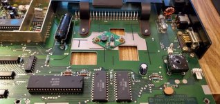
That wasn't so bad. Not happy with the temporary capacitor replacement on there, didn't have that value in stock so I did some cap math and got pretty close.

I did one brief test before I went to bed last night, and it powers up. Next step is to check the ripple on the 5V rail to make sure it's reasonably low. Glitch recommended that I throw a tantalum capacitor on there if it's a problem, and that should work fast enough to combat the ripple. After that, it's time for extended operational tests and monitoring with a temperature probe.

Have any of you tried similar linear to switching upgrades on Commodore machines? Success stories, failures, etc. are all welcome.
 
TTL logic is fairly tolerant to ripple on its 5V supply even a few hundred millivolts of ripple or RF hash would be tolerated. Even with a linear regulators powering the 5V rail, like an LM309k, it ends up with noise, not just due to the regulator, but due to the switching activities of all the logic circuit it supplies, despite bypass capacitors on the IC's.

Obviously it is a good idea or notion to reduce heat dissipation, but it depends why you want to do it. If the heat sinking on the linear regulator is adequate (so it does not run too hot) and the cabinet ventilation is good, there is usually no worry. So my preference would be for an original linear regulator. If you want to get very beautiful LM309k's, original gold plated vintage National Semiconductor types, last time I looked they were still available from Surplus Sales Nebraska.I trust these more than the new ones.

The only one thing I would worry about with the replacement switching regulator, is a possible failure mode where it could apply the input voltage to its output and then destroy most of the IC's in your computer. It could be devastating. So I would have to be 100% happy that the circuitry on that module could not do this before I deployed one.

That sort of event is nearly unheard of with the LM309k (the genuine original type at least). So its one thing to think about.
 
Add a crowbar if you're worried about it applying full unregulated power. Many higher-end supplies include/included them, even in the old days.

Those EzSBC regulator modules seem to be well-regarded, a lot of them get used on S-100 systems since the heat dissipation on a really hot +8 rail (which can really be more like +10) will cook old cards. A lot of the s100computers.com boards are being used with the EzSBC modules.
 
There are commercial switching regulators that drop into a TO-220 78xx or 79xx spot. They could probably be adapted for TO-3 spots. AFAIK they do include overvoltage and overcurrent protection.
 
Add a crowbar if you're worried about it applying full unregulated power. Many higher-end supplies include/included them, even in the old days.
Considering this is a 2 prong VIC-20 power supply, I'm not all that worried. If it were a 4 prong supply on the CR motherboards, then the risk of getting an overvoltage fault from the previous regulation stage would be a concern. But that would be from the 5VDC section of that external power brick rather than the 9VAC, and thus it's irrelevant to this machine. I'm not particularly concerned about it at present.

There are commercial switching regulators that drop into a TO-220 78xx or 79xx spot. They could probably be adapted for TO-3 spots. AFAIK they do include overvoltage and overcurrent protection.
I see no need to adapt from a TO-220 when I've already found a TO-3 package that does current limit protection, thermal shutdown, and can tolerate up to 40V (which is the limit of the original 323 if memory serves).

Time to check the 5V rail ripple!
 
After several hours of running with the modifications, the machine is barely warm. The VIC chip, KERNAL and BASIC ROM's are the greatest sources of heat on the entire board at about 112F. The power regulation side of the board is barely above room temperature, and I'm starting to wonder why the diode bridge even has it's own heatsink considering it's only about 90F.

20190601_000502.jpg

Looking at the ripple on the scope, it seems to be pretty minimal, but it is certainly more noticeable than the linear counterpart. The spikes are rhythmic and pretty sharp, and so I think it might be time to throw a capacitor on the output side to see about smoothing that out. Not sure what value of tantalum to throw at the problem yet...

Oh, and the unmodified VIC? I didn't measure the temperature when I had it running on the bench, but I can tell you that the regulator heat sink was hot enough that I don't want to touch it... again.
 
Oh, and the unmodified VIC? I didn't measure the temperature when I had it running on the bench, but I can tell you that the regulator heat sink was hot enough that I don't want to touch it... again.

That sort of thing suggests that the regulator heatsink was too small in total surface area. Its always a bad sign when a power device is running so hot you cannot hold your finger on it for at least a couple of seconds. It usually means it requires a heatsink with a lower thermal resistance. Its best to put a temperature probe on it too. Although silicon devices can be rated for 90 deg C and much higher, most likely the life is shortened running at the high end of their temp ratings.
 
That sort of thing suggests that the regulator heatsink was too small in total surface area. Its always a bad sign when a power device is running so hot you cannot hold your finger on it for at least a couple of seconds. It usually means it requires a heatsink with a lower thermal resistance. Its best to put a temperature probe on it too. Although silicon devices can be rated for 90 deg C and much higher, most likely the life is shortened running at the high end of their temp ratings.
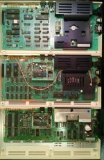
It's my understanding that this was a problem with the VIC-20 from the get-go. The original production version, and the more common Rev E each rely on those massive heat sinks. Fortunately, the case prevents the user from touching the metal, but it still isn't an ideal situation for someone who enjoys using a VIC-20 to know the computer is cooking itself.

mobos.jpg
It would explain the CR overhaul moving towards to external 5V regulation when the time came.
 
I did something similar with a CR VIC (external regulator version) but for different reasons. I wanted a more efficient supply that would run from a 12 V battery and, since those supplies are known to fail taking out the VIC, one that was protected from overvoltage. It includes a (not fully tested) crowbar circuit that may be of interest. If you are interested it is documented here http://wrcooke.net/classiccomputer/vicpower/vicpower.html
 
I had been thinking about painting the dinged up case of this VIC-20 for some time, but I finally got around to it. The keyboard being a C16/VIC hybrid made it a perfect candidate. Well, here are the results:

VIC glamour shot.jpg

VIC top.jpg

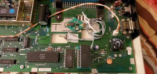
As for the motherboard, I found a correct value of capacitor to replace the funky combined approach. I also removed the soldered KERNAL ROM and installed a bank selection socket that's compatible with modern EEPROMs. Right now, I have it populated with a slightly modified version of the KERNAL that changes the default color pallet.

20190610_025504.jpg
 
Back
Top