
| VCF West | Aug 01 - 02 2025, | CHM, Mountain View, CA |
| VCF Midwest | Sep 13 - 14 2025, | Schaumburg, IL |
| VCF Montreal | Jan 24 - 25, 2026, | RMC Saint Jean, Montreal, Canada |
| VCF SoCal | Feb 14 - 15, 2026, | Hotel Fera, Orange CA |
| VCF Southwest | May 29 - 31, 2026, | Westin Dallas Fort Worth Airport |
| VCF Southeast | June, 2026 | Atlanta, GA |
-
Please review our updated Terms and Rules here
-
From now on we will require that a prefix is set for any items in the sales area. We have created regions and locations for this. We also require that you select a delivery option before posting your listing. This will hopefully help us streamline the things that get listed for sales here and help local people better advertise their items, especially for local only sales. New sales rules are also coming, so stay tuned.
You are using an out of date browser. It may not display this or other websites correctly.
You should upgrade or use an alternative browser.
You should upgrade or use an alternative browser.
WANTED: Eagle CP/M Computer mainboard repair
- Thread starter owensct
- Start date

Chuck(G)
25k Member
Your location might be helpful!
Are these the original AVL Eagles or one of the later ones (e.g. Eagle II)?
Are these the original AVL Eagles or one of the later ones (e.g. Eagle II)?
Last edited:
zippysticks
Veteran Member
From previous posts looks like he was after Eagle IIe board support.
Be great to get more data about what the problem board symptoms are too.
Be great to get more data about what the problem board symptoms are too.
Hi Guys,
Sorry for the late reply I forgot to set it to notify me of any replies to the post.
In answer to your questions. The boards are from the later Eagle II series. My location is in San Angelo Texas, USA. At this point I have 3 boards and I am seeing the following symptoms:
1. The original board that was on the Eagle IIe I bought the symptoms are as outlined in this post I made. It displays on the CRT and the drives seek and it boots when a disk in inserted in drive A
http://www.vcfed.org/forum/showthre...r-need-help-advice-with-CRT-issues&highlight=
2. Then I bought a used board off of Ebay and it likewise has video problems, it consistently displays the attached screen whenever its powered on. The display fires up CRT and the drives seek and it boots when a disk in inserted in drive A
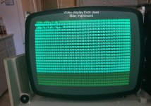
3. The 3rd board I got is completely dead, the power led on the board light up when I power on the computer, but nothing else, no drive seeks, nothing on the CRT
At this point I've gone over two of the boards with my loupe looking for corroded pins, bad sockets, loose components or wires, broken traces etc and as far as I can tell everything looks good.
Gordon
Sorry for the late reply I forgot to set it to notify me of any replies to the post.
In answer to your questions. The boards are from the later Eagle II series. My location is in San Angelo Texas, USA. At this point I have 3 boards and I am seeing the following symptoms:
1. The original board that was on the Eagle IIe I bought the symptoms are as outlined in this post I made. It displays on the CRT and the drives seek and it boots when a disk in inserted in drive A
http://www.vcfed.org/forum/showthre...r-need-help-advice-with-CRT-issues&highlight=
2. Then I bought a used board off of Ebay and it likewise has video problems, it consistently displays the attached screen whenever its powered on. The display fires up CRT and the drives seek and it boots when a disk in inserted in drive A
3. The 3rd board I got is completely dead, the power led on the board light up when I power on the computer, but nothing else, no drive seeks, nothing on the CRT
At this point I've gone over two of the boards with my loupe looking for corroded pins, bad sockets, loose components or wires, broken traces etc and as far as I can tell everything looks good.
Gordon
Chuck(G)
25k Member
Well the photo shows that there are two possibilities: (1) the CRT8002 character generator is bad or (2) something in the path from RAM feeding it is. The CRT display uses a 2Kx8 static RAM (M58725, U607). While the SRAM is very easy to source (generic 2KB 24-pin SRAM) and would be the easiest to check, the CRT8002 has long been out of production and might be harder to scrounge up.
Last edited:

Jove
Experienced Member
For board 2, based on the Characters we can see it looks like D6 (0-7 numbering, 64's place) is stuck on.
That is the only bit commonly on or off for the ASCII values of
iSzivSY
I would have expected @ symbols (0x40) for the entire screen, but I am not familiar enough with Eagle to know if blank screen characters are represented in video memory as null or space (0x00 or 0x20). If they are stored as space, then the screen should be filled with backticks (0x60).
It is also possible that D7 is also stuck on but is ignored for most characters? does D7 get used for other video properties like inverse on the eagle machines?
That is the only bit commonly on or off for the ASCII values of
iSzivSY
I would have expected @ symbols (0x40) for the entire screen, but I am not familiar enough with Eagle to know if blank screen characters are represented in video memory as null or space (0x00 or 0x20). If they are stored as space, then the screen should be filled with backticks (0x60).
It is also possible that D7 is also stuck on but is ignored for most characters? does D7 get used for other video properties like inverse on the eagle machines?
Chuck(G)
25k Member
According to the CRT8002 datasheet, space is at 2/0, or hex 20h, where you'd expect.
Those are kind of the conclusions I came to by reading some other posts about the Eagle, but my skill at board level repair are pretty much non-existent, (I've replaced some bad caps before and that's about it). Now that I have 3 boards, one of which is dead I figure I can practice my board level repairs on the dead board and not have to worry about screwing it up. I've got to locate the chips that "may" be bad, I don't read schematics very well, and see what's involved in replacing them.
Thanks
Gordon
Thanks
Gordon
ldkraemer
Veteran Member
It looks to me like the Text that should be displayed is mostly lower case with
a splattering of Graphics for the SPACE 0x20.
For the Video RAM, I'd look at D5 with an O'scope while 0x79 filled the screen in a loop.
for the SPACE = 0x20 = 0010 0000 what in your Character Set is 0000 0000 ??
Larry
a splattering of Graphics for the SPACE 0x20.
iSk drive A not readY
uSH anY keY to try again
Code:
D  0x44 vs ox64   = 0100 0100 vs 0110 0100 = Bit 5 Different
i  0x69
S  0x53 vs 0x73   = 0101 0011 vs 0111 0011 = Bit 5 Different
k  ox6B

d
r
i
v
e

A

n
o
t

r 0x72
e 0x65
a 0x61
d 0x63
Y 0x59 vs 0x79   = 0101 1001 vs 0111 1001 = Bit 5 Different
For the Video RAM, I'd look at D5 with an O'scope while 0x79 filled the screen in a loop.
for the SPACE = 0x20 = 0010 0000 what in your Character Set is 0000 0000 ??
Larry
ldkraemer
Veteran Member
I located the Service Manual for the Eagle on Bitsavers. It explains the 8002 and 5037 pretty well.
p.46
p.129
Bits 0 through 6 of Register 0x31 = 2 ^ 7
Bits 0 through 5 of Register 0x32 = 2 ^ 6
With this information and a small program in assembler, you should be able to write a "Y"
out for maybe 127 characters and chase D5, BD5, and VD5 from U304, to U306, to U307,
to U709, to U708, to U707, to U706 and to U608 with your O'Scope.
Larry
p.46
CRT 8002 & 5037
The 8002 Video (Character) Generator LSI and the 5037
Video/Timer Controller LSI make up the majority of the
video section. The 8002 contains a predetermined character
set, 128 alphanumeric characters and graphic symbols. When
a character is to be output to the CRT, the address of the
character is placed on the address bus of the 8002 by the
microprocessor. When the 8002 is selected, this character
address is input to the 8002. Then, in time with the video
dot clock, the character selected is output in serial fashion
to the CRT.
The only attribute selection used by the Eagle system is
reverse video. When reverse video is selected, the reverse
video line is pulled high and the character data is inverted,
before it is placed in the serial output shift register of
the 8002.
The other part of the video section is the 5037. This LSI
is not pre-programmed. It is programmed with seven 8-bit
words that define for the 5037 the horizontal and vertical
format of the CRT display. This information is stored in
the 2732A Boot EPROM, and loaded as part of the initial
loading sequence. The information includes the size of the
display, the size and spacing of the character blocks, and
the vertical and horizontal scan rate. The 5037 also provides
the cursor mode information to the 8002.
p.129
VIDEO DISPLAY
A register at port 31H holds the cursor column position
in bits 0 through 6, and a register at port 32H holds the
cursor line number in bits 0 through 5. The bits in these
registers are used to address the 80*24 video buffer.
READY is located at port 30H, bit 7. When this bit flag
is set true a byte of data may be written here. At port 33H
is the register which is used to write data to the video
buffer.
The video controller chip is an SMC CRT5037 and occupies
a 16 byte port block which begins at port 80H.
(See Figure 16.)
Bits 0 through 6 of Register 0x31 = 2 ^ 7
Bits 0 through 5 of Register 0x32 = 2 ^ 6
With this information and a small program in assembler, you should be able to write a "Y"
out for maybe 127 characters and chase D5, BD5, and VD5 from U304, to U306, to U307,
to U709, to U708, to U707, to U706 and to U608 with your O'Scope.
Larry
Last edited:
ldkraemer
Veteran Member
I had previously had extracted the files from an Eagle Image File and the "EBIOS.ASM"
file can help you build a small test routine.
Send me PM with your email address.
Larry
file can help you build a small test routine.
Send me PM with your email address.
Larry
Hi Guys,
Wow!!! Lots of information, but unfortunately I don't have the knowledgebase to apply the things you guys are recommending. Heck I don't even own a scope or know how to use one. Not that I'm opposed to learning, but you'll have to really dumb it down for me. That's why I was looking for someone who could do board level repairs for me, as I don't yet have the skills necessary to repair it myself.
I just wanted to drop you guy a quick note to let you know that I'm still here. I need to carefully re-read everything you posted to see what I can understand and ask questions.
Thanks for the help.
Gordon
Wow!!! Lots of information, but unfortunately I don't have the knowledgebase to apply the things you guys are recommending. Heck I don't even own a scope or know how to use one. Not that I'm opposed to learning, but you'll have to really dumb it down for me. That's why I was looking for someone who could do board level repairs for me, as I don't yet have the skills necessary to repair it myself.
I just wanted to drop you guy a quick note to let you know that I'm still here. I need to carefully re-read everything you posted to see what I can understand and ask questions.
Thanks for the help.
Gordon