hunterjwizzard
Veteran Member
- Joined
- Mar 20, 2020
- Messages
- 2,302
Hey that's really cool! I have no idea what it is. But that is really cool that you're trying to identify all of them!
| VCF West | Aug 01 - 02 2025, | CHM, Mountain View, CA |
| VCF Midwest | Sep 13 - 14 2025, | Schaumburg, IL |
| VCF Montreal | Jan 24 - 25, 2026, | RMC Saint Jean, Montreal, Canada |
| VCF SoCal | Feb 14 - 15, 2026, | Hotel Fera, Orange CA |
| VCF Southwest | May 29 - 31, 2026, | Westin Dallas Fort Worth Airport |
| VCF Southeast | June, 2026 | Atlanta, GA |

Thank you...I MAY have just done it! Now for the mystery big-iron peripherals next...another day!Hey that's really cool! I have no idea what it is. But that is really cool that you're trying to identify all of them!
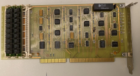
Anybody know what this item from "The Tabulating Machine Company" is for ?
Its oldest item I own now I think (as the company went up in IBM in 1933 if I am not mistaken).
View attachment 1292624View attachment 1292625

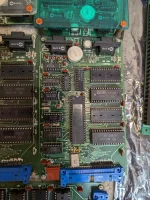
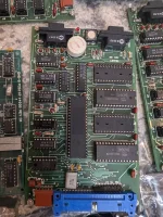
I'm sure you have looked for the TEANEY 88 [as I did]. It is a bit of a stretch, but there is an EE , Dale Thorpe Teaney and he has mentored students who did 8052 Projects (https://digitalcommons.njit.edu/theses/2813/). Perhaps it is his design?Less of a "mystery" item, as I know what its supposed to /DO/ but more of a mystery company/mystery info situation?
View attachment 1292780View attachment 1292781
(I know its an 8052AH-Basic 'trainer' board, but i'd love more info, and/or maybe someone who's sussed out the circuit diagram? I've got a bunch of them with the 8052AH-BASIC chips and SRAMs on them, but on pretty much every one there's leaky-battery residue-to-possible-PCB damage on the board opposite the blue edge connector?))
Gawd dang! That's basically the EXACT DESIGN of the board I have, aside from a few component labelling gaffes. (R10/R14 being actually R16/R14, and the Second (rectangular) C1 being actually D1, but that's off the top of my head/what stands out most to me)I'm sure you have looked for the TEANEY 88 [as I did]. It is a bit of a stretch, but there is an EE , Dale Thorpe Teaney and he has mentored students who did 8052 Projects (https://digitalcommons.njit.edu/theses/2813/). Perhaps it is his design?
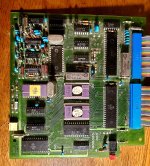
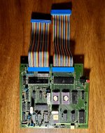
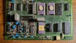
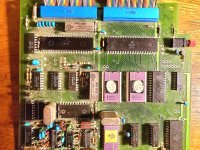
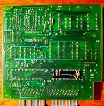
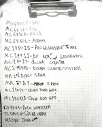
Do you mean Rx and TX data pins on the modem?It’s a neat little single board computer, but… yeah, without dumping the ROMs it’s hard to even guess what it was *for*. It looks like the address and data lines from the CPU are routed straight to the neighboring ribbon cable in addition to the peripherals on the board, so it’s very possible there was a lot more to it originally.
Edit: can you trace where the analog input/output from the modem chip terminates?
And yeah, this may be just the brains of a larger system.
Do you mean Rx and TX data pins on the modem?
I don't think I'm yet able to send DMs, since my posts are only (seemingly at 7 or so) so not sure if you got my response about YOUR question about buying a board for restoration. Let's just chat here for a bit about the boards till my post count gets high enoughI'm sure you have looked for the TEANEY 88 [as I did]. It is a bit of a stretch, but there is an EE , Dale Thorpe Teaney and he has mentored students who did 8052 Projects (https://digitalcommons.njit.edu/theses/2813/). Perhaps it is his design?
I did consider that but don't know enough about that chip to evaluate if that would be an easy way to do a cassette interface. That relay on the board certainly could be for one or the other. Not sure what else it would be doing there.The presence of that opamp on the board makes me kind of wonder if instead of using that chip as a telephone modem they might have been doing something like using it to drive a cassette interface?
I did respond in DM and it looks like you also saw and responded. You will be up to 10 soon I guess, but, for continuity, yes, I am interested in trying to get a board working because it sounds like a fun project (famous last words) and it looks like they are genuine Intel chips from 87-88 (I could be wrong). The longer response is in DM.I don't think I'm yet able to send DMs, since my posts are only (seemingly at 7 or so) so not sure if you got my response about YOUR question about buying a board for restoration. Let's just chat here for a bit about the boards till my post count gets high enough
Would you possibly be able to restore one of them for me if I sold you a few yourself? (And/or help me be able to restore MY own boards in the process?)
Yeah, there's no headers on the board besides the two that the ribbon cables are connected to.I was thinking the... (looking at the datasheet for the part).. Tx and Rx carrier pins. (Pins 10 and 17?) Not Tx/Rx Data, which are the serial pins going to the UART. The datasheet describes how those pins in a standard modem application would go to external filters and a phone duplexer, but I don't see an obvious header to connect to a phone jack...
The presence of that opamp on the board makes me kind of wonder if instead of using that chip as a telephone modem they might have been doing something like using it to drive a cassette interface?
