• Please review our updated Terms and Rules here

XTIDE tech support thread

Edit: Looking more closely at the CF adapter i can see that Pin 28 from the IDE header is connected to Pin 16 (A04) and Pin 14 (A06) of the CF header, Looking at another different CF adapter i can see that Pin 28 from the IDE header to the CF header is NC. So why the 2 address pins are conected to IDE pin 28 i don't know ?

That's even more interesting, as address lines beyond A02 are not used when a CF card is operating in IDE mode. Why would the adaptor designer connect them to /anything/??

I just found out why, I missed the fact that Pin 28 of the CF adapter IDE header is also connected to Ground, Pins 22-24-26-28-30 are all grounded as are pins 2-19-40. So when i removed Pin 28 from the controller IDE header the machine booted successfully.

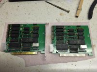
On this Controller card Pin 28 of the IDE header is directly connected to B28.

Great stuff!

It would be interesting to know some background around that particular pin. I might dig up some IDE HDDs when I get home later and see what their pin 28 connects to.
 
I dug out some more IDE/Floppy/Multi IO controller cards, On the older cards which uses 74 series IC's, Pin 28 of the IDE header is connected to a 74 series (244) IC. These cards work fine with this CF adapter.

On the newer cards which uses ASICS, Pin 28 of the IDE header is directly connected to B28, Hence the no boot situation using this CF adapter with IDE pin 28 grounded.
The easiest solution is to snip off / remove pin 28 from the CF adapter as it's not required (from what i've been reading) anyway. Rather than remove the pin from the controller card.
 
Last edited:
IDE (c.1986) was designed to work directly with ISA and originally, IDE pin 28 was also ALE:

http://pinouts.ru/HD/IdeInternal_pinout.shtml

Later, with ATA in 1992 the T13 standards committee changed this pin - since it wasn't needed - to cable select, possibly the most-inconsistently-yet-should-have-been simple part of the standard. All the host has to do is ground it, then the drives (with PU resistor) can determine their cable position. But I digress!

Well there you go! Thanks for the info.

So isolating pin 28 of the IDE header and connecting it to ground should be sufficient to get most IDE-CF adaptors working on most ISA IDE controllers.

Or just buy an XT-CF :p
 
So isolating pin 28 of the IDE header and connecting it to ground should be sufficient to get most IDE-CF adaptors working on most ISA IDE controllers.
That would seem trivial enough: both adjacent pins are ground. This is a mod even I might try to do (in spite of my poor eyesight).
 
Last edited:
Is there a sheet that tells you which resistor value goes in which space on the XT-IDE v2? I looked everywhere and can't find anything. The capacitors are labeled with values, but resistors aren't. R8, R6, R5... It would be nice to know which value goes in these spaces.

Information seems to be scattered all over the place.
 
Also see the xtide build instructions, There are 6 resistors R2 - R7 which are all the same and the other 2 resistors go in R1 and R8, Also see the note on Resistor R6 here. A while back Heather posted a pic of her xt-ide R2 build.
 
Likely 10k will work everywhere. Note that CSEL should be tied directly to ground (use 0R resistor or just a bit of wire).
 
thanks. Got it built.

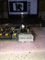
Is the molex connector installed right? I'm just extra cautious because I don't want to fry this thing. The pins aren't labeled on the pcb

Photo Mar 25, 4 57 51 PM.jpgPhoto Mar 25, 7 32 13 PM.jpg
 
Is the molex connector installed right? I'm just extra cautious because I don't want to fry this thing. The pins aren't labeled on the pcb
Yes.

Jameco part 117568 is the intended part. Description/diagram at [here] (2 pages).

1. Your part is either a Jameco part 117568, or is equivalent; and
2. The photo at http://www.vcfed.org/forum/showthread.php?29202 shows that the connector sits on the component side.
 
Yes.

Jameco part 117568 is the intended part. Description/diagram at [here] (2 pages).

1. Your part is either a Jameco part 117568, or is equivalent; and
2. The photo at http://www.vcfed.org/forum/showthread.php?29202 shows that the connector sits on the component side.

Yup, got it from Jameco. Ok, good, it's correct. That's only hooked up if you want the power on the unused IDE pin powered, correct?
 
Yup, got it from Jameco. Ok, good, it's correct. That's only hooked up if you want the power on the unused IDE pin powered, correct?
No. Do not run power into that connector. The connector is for powering external devices. To quote the VCF Wiki: "Onboard power connector for powering either CF devices (5 volts) or standard HDDs (12 volts) for machines without spare wiring from the power supply (such as the IBM model 25)."

If you have an IDE device that can be powered via pin 20 of the IDE connector, then all you need to do is put a jumper on P9 (that routes +5V through to pin 20 on the IDE connector).

Nice. Thanks.
 
Has anyone tried a WD1002-WX1 controller alongside the XT-IDE card?

I'm trying to get high-density floppy support working in my Tandy 1000.

Basically, the xt-ide controller doesn't function at all, no bios menus are available or anything. I'm suspecting a ROm address conflict but I haven't added the optional components to enable switching XT-IDE address...

<edit>

Sorry, it just occured to me that there are several XTIDE devices.

I'm using the https://www.lo-tech.co.uk/product/lo-tech-isa-compactflash-pcb/
 
Last edited:
Hi everyone,

Hopefully this is the right thread for this...but anyway...

A while ago I got an XT-CF-Lite card for some of my PC-XT clones. I wrote about my initial experiences in this blog post where I mentioned formatting difficulties. Anyway, I thought things were stable but I was playing with it recently and noticed some more problems. The main symptom was that writing to the card in a vintage machine (when emulating a hard disk) seemed to invariably corrupt files, often to the extent where the card couldn't be booted from. The problem was resolved when I changed the card. I had been using a 4GB card. Somewhere in the junk box I found and unused 10MB one (yes, 10MB!) from a VERY old digital camera. This one seems to work just fine.

I'm now thinking that 4GB was perhaps just too big. Both MS-DOS 6.22 and my windows XP machine only recognises this card as being 2GB in size. I'm assuming this is due to the card being formatted in FAT 16 (I'm assuming this is case, yes?). Has anyone else had a similar experience with these large capacity cards not working well? I read somewhere that these cards are built to be FAT32 only? Is it best therefore, just to use a card under 2GB?

In a different but related problem, my XP machine recognizes (i.e. it can see files and folders) but can't seem to read from or write to this 10MB card? It's a really old card (late ninties?) so I'm assuming it's a speed issue? Anyone know? There is no problem reading and writing when in the XT-Lite-CF device.

Ten MB is a bit small and has the problem described above so I'm looking then to get a card that both works reliably with the XT-CF-Lite device AND can be read and written to by my PC. I'm wondering if it's simply best to avoid the large capacity cards, or if my particular 4GB one (a generic Dick Smith model) was simply incompatible? Any comments?

Tez
 
Back
Top