patscc
Veteran Member
coffee
coffee
I especially like the last trace...give your PET less coffee...
patscc
coffee
I especially like the last trace...give your PET less coffee...
patscc
Heh - it does look pretty energetic, yes! Any suggestions on what I should replace while I'm at it? If I need to remove the video board, I'd rather just do it just the once...I especially like the last trace...give your PET less coffee...
I have a replacement for C3, so I was planning to stick that on in parallel and see if it helps any. I don't have a replacement for C1, but will pick one up tomorrow if necessary. Rectifier appears OK but I'll give it a proper look tonight. An external 12V is a great idea - I'm sure I have an AT power supply around here which would do the job.The schematic I have has the 12V coming from a 7812 fed by a seperate bridge rectifier. I'd check the caps & rectifier. If you have a 12 VDC source handy, you can just disconnect the out of the 7812 and feed in 12V, and see if the ripple clears up.
Not sure what you're looking for - the one I linked to is the only video board schematic I have, which came from here. The rest of the machine is later, so I've been working from these.I have to run, do you have a link to more schematics ?
Only thing left now is that skinny column and the wrap-around on the right-hand side. I did manage to get a trace of test point 13 while the video board was out. Going by the illustrations, I'm pretty sure that big "M" bit (to use the technical term) is correct, but those two little peaks preceding it shouldn't be there. Could they correspond to the narrow column and horizontal wrapping?
BTW: the collector of Q14 isn't actually connected to anything, although according to the parts layout this is apparently correct for the TIP55A fitted(?)
Are we looking at the same docs? My video board is an early version (schematic here). Unfortunately the illustrated waveforms are not very clear and have no scales. I believe TP13 on this board corresponds to TP17 on the newer 2001N version. Just to confuse matters, both TP13 and TP17 on the new schematic have a period of 64uS ;-)Comparing your signal with TP13, the overall period of 64 uS is correct, but the positive period should be 24 uS, so to me should not the the positive time period incorporate all the pulses you see big and skinny?
And how about the signal amplitude? It does not looks correct. Are you using a 10X probe? The schematic seems to indicate 0.5V peak, is that correct?
You are doing a great job.
Yep, input is TTL and TP3 on the old schematic (coincidentally, TP13 on the new one!) looks to be a bit busier on the scope than it ought to be. I don't really get this part at all, as if it's that different I wouldn't expect the effect at the CRT to be so subtle.Looking at the documentation again, the Horizontal Drive input to the video board is TTL level (~5V), is that correct? So either the source is bad or something on the video board or elsewhere is loading it down in a weird way.
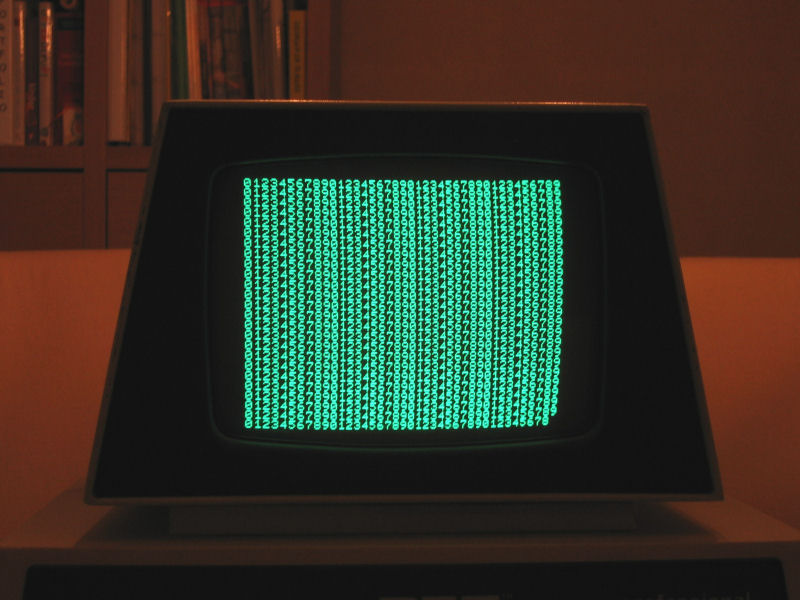
The screen looks pretty much like it did before here, but then stable and without the bowing in at the top. The narrow column is the 31st from the left, if I'm counting correctly. The last 3 or 4 characters on each line also "double back" on their predecessors.Cosam, could we get a pic of the screen how it looks now ?
Oh, there's definitely been someone in there before me, yes. Some transistors have been replaced but I think only Q11 in the horizontal circuit - I'll whip it out again and check. I resoldered all the repair-looking pins just in case, but no joy.The peaks could be some ringing, the band you describe sounds like there's some sort of phase shift going on in the hor. circuit. Does the board look like it's been repaired before ?
The replacement Q11 is the correct part and everything else looks to be original. C28 is the real deal and even still glued in place. The flyback could be a replacement, but it's neater than the rest so probably just manually soldered at the factory.Can you check to see if the caps & parts in the hori. drive & output stage are the same as in the schematic ?
Is C28, the 10uF non-polarized, actually non-polarized ?
Glad to: http://www.cosam.org/images/pet/scope7.jpg. Hope you can make more out of it than I could!Oh, can you connect your scope to 11 and see what you get ?
Yep, both are correct and look to be the original parts.So Q12 is the actual PNP it's supposed to be, and Q13 is correct as well ?
Here's TP3 (and are you kidding? I really appreciate you taking the time to look at them!)Waveform at 3 ? (Sorry I'm bugging you with all the different measurements, I unfortunately can't just pop 'round and take them myself)
Here's TP3 (and are you kidding? I really appreciate you taking the time to look at them!)
Ah yes - garbage in, garbage out, as they say. At least we're back in the realm of things I understand.cosam, TP3 doesn't look at all like the picture in the docs. Start checking the Horizontal Drive circuit in the main logic board. Maybe the 12 V regulator was all that was wrong with the video board. The Horizontal Drive circuit should not be at a high level so long. Look at the signals called Display On and Display Off. They are at JK flipflop C5 pins 5 & 6.
Heh - the real stinker is that the culprit was literally just one component away from the header on the video board schematic you were most probably looking at. Physically of course a different board and a different page! Don't get too upset - you deserve all credit for catching the 12V ripple problem ;-)Hey, no fair ! The schematic I've got doesn't show the flip-flop. Where do y'all get the good stuff from ?
It was almost an anticlimax when it finally worked, but the grin-factor is sinking in, yes ;-) Now that the causes are known, maybe you should have a browse through the schematics? You might understand more than you think!Even though I didn't understand most of the electronics involved (hopefully I will someday), it's great to see people helping each other in bringing a classic micro back to life. I'll bet you feel very satisfied.