• Please review our updated Terms and Rules here

Zilog Z80 homebrew computer rs232 problem

Sendraz

Member
Joined
Apr 8, 2022
Messages
16
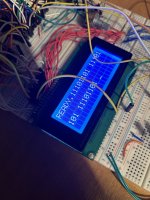
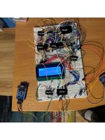
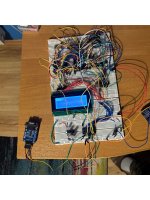
Hello, i have currently almost built my project, which is a Z80 computer made from scratch on a breadboard with motorola 6850 ACIA with which i have a problem. It is connected to 1.8432 mhz crystal oscillator like the cpu, and i can send data with it from the z80 to the PC terminal, but when i send characters to the z80, it receives interrupt, but the received data is something like 11101101 in binary, or sometimes 00000000 depending on which character i input on my computer.

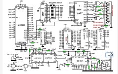
I dont have a proper schematics for this yet, but i have labeled where everything is on the photos, and i can describe how the ACIA is connected:

VCC - +5V
VSS - GND
RX_DATA - RxOut (rs232 to uart converter)
TX_DATA - TXin (rs232 to uart)
RX_CLK - 1.8432mhz crystal
TX_CLK - 1.8432mhz crystal
RTS - RTS (rs232 to uart)
IRQ - Z80 IRQ
CS0 - +5V
CS1 - +5V
CS2 - Y2 (74hc138 demultiplexer)
E - +5V
CTS - GND
DCD - GND
D0-D7 - D0-D7 (Z80)
R/W - WR (Z80)

The rs232 to uart is used temporarily, but with max232 + db9 connector it works the same.
 

Attachments

  • IMG_0576.jpg
    IMG_0576.jpg
    1.4 MB · Views: 16
  • IMG_0574_labeled.jpg
    IMG_0574_labeled.jpg
    2.4 MB · Views: 16
  • IMG_0574.jpg
    IMG_0574.jpg
    2.4 MB · Views: 16
  • code.txt
    1.6 KB · Views: 2
The E signal on the 6850 is a clock signal, not a static value. Invert the /IORQ signal from the Z80 and use that as your E clock. It's not quite what the 6850 expects, but it's close enough that it works on the RC2014 boards.

Your transmit and receive clocks are way too fast. They need to be below about 830 KHz to work at all. They also need to be 1x, 16x, or 64x your desired serial data rate.
If you take a 74LS92 divide by 12 counter and use that to divide the 1.8432MHz clock, you get a 153.583 KHz clock, which is exactly 16 x 9600 baud.
 
Cool, i will go with the 74LS92 because i couldn't find any crystal that has frequency that is divisible, and i will connect E to ~/IORQ.
The E signal on the 6850 is a clock signal, not a static value. Invert the /IORQ signal from the Z80 and use that as your E clock. It's not quite what the 6850 expects, but it's close enough that it works on the RC2014 boards.

Your transmit and receive clocks are way too fast. They need to be below about 830 KHz to work at all. They also need to be 1x, 16x, or 64x your desired serial data rate.
If you take a 74LS92 divide by 12 counter and use that to divide the 1.8432MHz clock, you get a 153.583 KHz clock, which is exactly 16 x 9600 baud.
 
I'm wondering why you didn't use a more friendly USART chip, like the 2650. None of this trying to make a x80 bus work with a 68x peripheral.
 
I'm wondering why you didn't use a more friendly USART chip, like the 2650. None of this trying to make a x80 bus work with a 68x peripheral.
Well, i was thinking about getting an z80 SIO, but for some reason thought that the 6850 will be good, because some other homebrew z80 projects used it, now i know it wasn't a good choice for this, but since i have one, i want to use it anyway. Maybe if somehow it stiill wont work with lower clock speed then i will order other chip.
 
So today i installed a 74ls92 and connected E to ~/IORQ, but still the same problem. The same binary number as on the photos is displayed instead of correct ascii character. Can it be something with using the breadboards? or i just have to replace the chip with other one, more compatible with z80?
 
So today i installed a 74ls92 and connected E to ~/IORQ, but still the same problem. The same binary number as on the photos is displayed instead of correct ascii character. Can it be something with using the breadboards? or i just have to replace the chip with other one, more compatible with z80?
It is an interesting question whether the breadboard arrangement could be responsible. The arrangement certainly has more inductance in the interconnects than there would be in a pcb design.

It may not in fact be anything to do with your troubles, but I zoomed up on the images and I cannot see many power supply bypass capacitors, really you should have a good number of 0.1uF monolithic ceramic capacitors on all of the power supply rails, especially as close to the chips power pins as possible. Where the blue and red power rails are sprinkle, them along those rows.

Probably, bread boarding something like this, it might be better to do it on plated through hole spot board with IC sockets, where you can first set up the power supply distribution to the IC's and the bypass caps, and then do the wiring in an orderly manner, it works well to use wire wrap wire and to solder it. One trick is to route the wires so you don't lose access to the pins of the IC sockets. There is a hand wired prototype on spot board in this article which shows the method to keep the wiring orderly on pages 11 and 12 and maintain access to the IC socket connections:

www.worldphaco.com/uploads/LIGHTPEN.pdf

In any case, it is hard to know for sure if the power supply bypassing (or lack of it) or the Bird's nest configuration could be hampering the outcome. It could be easy to blame that, when something entirely different could be giving your troubles.
 
I have added some capacitors, and still no luck. I guess i must go with the dart or sio. Which one is better?
 
I dont know if there is also a possibility that my chip is just broken. While i ordered it, i noticed the legs on it were looking like they were broken off and soldered again. It seems like the chip receives data from the cpu and sends it to the pc flawlessly, but the Z80 cant read anything from it.
 
Have you tried polling instead of using the interrupt? Generally, hardware write accesses are more forgiving than read accesses. Have you verified the timing for /E and R/W with an oscilloscope to make sure that you are within specification? Can you reliably read back the configuration registers?
 
Have you tried polling instead of using the interrupt? Generally, hardware write accesses are more forgiving than read accesses. Have you verified the timing for /E and R/W with an oscilloscope to make sure that you are within specification? Can you reliably read back the configuration registers?
I've tried polling, with the same result (11101101) no matter what. When i tried to read config registers, it always returns 11111101 in loop for some reason, like the interrupt would trigger every time.
 
I don't know the 6850, but your description sounds to me as if you are simply unable to read data from the chip. Configuration and transmission do not require reads to be functional, but data reception certainly does. Try to find a register you can freely read and write and make sure that you actually can communicate with the chip in both directions.

Maybe your timing on the /E or R/W pins is marginal, the Z80 bus cycle is too fast, or the data is expected at the wrong time. An oscilloscope or logic analyzer should allow you figure out whether the UART tries to respond correctly in the first place and is misunderstood by your system, or if it actually is broken.
I have tried now to read status register, it returns 00000000, the control register is write only, but i can write to it because could set the interrupts and frequency division.
 
You obviously can write correctly to the chip because you can transmit UART data.
You haven't proven that you can correctly read from the chip. :)
Time to bring out the big guns, but I can't help you unfortunately.
 
If you could post your exact schematic around the 6850 UART might help.

Sometimes if I run into trouble getting an IC running as expected, as well as looking at the data sheet, I look at an example circuit that is known to work using it. This helps to check every pin is used properly.

The only circuit I have with a 6850 in it , is the Votrax TNT, so I have attached that, it shows how this IC is normally hooked up with a CPU & Baud rate generator and a line driver IC.
 

Attachments

  • UART.jpg
    UART.jpg
    330.3 KB · Views: 9
If you could post your exact schematic around the 6850 UART might help.

Sometimes if I run into trouble getting an IC running as expected, as well as looking at the data sheet, I look at an example circuit that is known to work using it. This helps to check every pin is used properly.

The only circuit I have with a 6850 in it , is the Votrax TNT, so I have attached that, it shows how this IC is normally hooked up with a CPU & Baud rate generator and a line driver IC.
I dont have the schematic yet, but i can work on it tomorrow.
 
Back
Top