• Please review our updated Terms and Rules here

Cromemco dazzler replica project

Good catch! I have one of Hugo's boards - and indeed, IC23 pin 10 is not tied to Vcc as it should. Fortunately the board still works since this connection (one of the flip-flop "preset" inputs) will float high if disconnected - however I should put a little jumper there to fix this issue "just in case".
Its possible/probable that the 'error' was present on that version of the original board that Hugo copied. The others were down to me missing them.

Hopefully someone can get one of these boards up and running.
 
The aim was to recreate the board as built by Cromemco from the images Hugo so painstakingly produced. Most of the changes were things I had missed from Hugo's images, the only one that wasn't is pin 10 of IC 23.

I assume that the connections are correct for the logic specified originally ?
 
Last edited:
It is interesting the issue of pull ups on plain TTL, while they are recommended (not as a direct connection) but with a pullup resistor, typically 1k or thereabouts, there are a good number of professionally made TTL circuits, using 74 series parts, that left the inputs floating to assume a high logic state, there are a few inputs in Atari's arcade Pong for example. There are many other designs I have seen that omit them (for plain 74 series TTL's). One is a frequency counter made by Communications concepts, and they ground lines on DIP switches with diodes, for a switching option, but otherwise the floating input sits at logic high.

In the case of the Dazzler board IC 23 pin 10 was tied high by the designers. That small link was missing from my board it appears, it doesn't stop it from working, I think though, it is better to connect it as the designers had it, even though ideally it would have had a pullup resistor.

The foil patterns I used were Rev C , they were nowhere near as clear as the colored ones posted, I had fairly poor monochrome patchy images.

Also, one thing I noticed about the original foil patters, the geometry of the S-100 edge connectors appeared off. So I had to look up the geometry of the S-100 card and figure out how to exactly space the fingers. Whether this was due to geometric distortion of the images I had, or possibly the original boards were not quite right, I am not sure.

If you plan to use these boards in a SOL-20 like I did, it pays to move the position of the video output connector pins on the pcb, to avoid the card slides. Possibly other computers with different card slides might or might not have this issue.
As Dave pointed out above "best practice" for 74 series devices is to pull up inputs that need to be at logic 1 via a resistor to Vcc.

However, the designers of the Dazzler did not make any attempt to follow this practice. The Dazzler schematic shows over 2 dozen inputs to 74 series devices pulled up to 5V, and none do so via a resistor. "Fixing" this issue would involve making a lot of changes to the original board layout to add the pullup resistors, and since the original design apparently worked okay this is probably not worth the effort.
 
Last edited:
It is interesting the issue of pull ups on plain TTL, while they are recommended (not as a direct connection) but with a pullup resistor, typically 1k or thereabouts, there are a good number of professionally made TTL circuits, using 74 series parts, that left the inputs floating to assume a high logic state, there are a few inputs in Atari's arcade Pong for example. There are many other designs I have seen that omit them (for plain 74 series TTL's). One is a frequency counter made by Communications concepts, and they ground lines on DIP switches with diodes, for a switching option, but otherwise the floating input sits at logic high.

In the case of the Dazzler board IC 23 pin 10 was tied high by the designers. That small link was missing from my board it appears, it doesn't stop it from working, I think though, it is better to connect it as the designers had it, even though ideally it would have had a pullup resistor.

The foil patterns I used were Rev C , they were nowhere near as clear as the colored ones posted, I had fairly poor monochrome patchy images.

Also, one thing I noticed about the original foil patters, the geometry of the S-100 edge connectors appeared off. So I had to look up the geometry of the S-100 card and figure out how to exactly space the fingers. Whether this was due to geometric distortion of the images I had, or possibly the original boards were not quite right, I am not sure.

If you plan to use these boards in a SOL-20 like I did, it pays to move the position of the video output connector pins on the pcb, to avoid the card slides. Possibly other computers with different card slides might or might not have this issue.

I found the Rev C foils in a high quality scan, so it is admirable you got all that data correcly reconstructed from a source with much less quality.

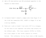
Concerning the changes of the design, I'd suggest to stay at the original Rev C design as is, independent of the discussion whether we need pullups or not (I see different sources with different statements concerning the necessity of pullups with bipolar TTL inputs, the most plausible for me is that if no pulldown resistor is required, also no pullup is necessary, with the exception of switches controlling the input level which of course need a resistor between the potentials). There is, however, at least one change of the Rev C design I would follow, as suggested under (3) in the Dazzler Games Manual which probably causes some problems with certain hardware setups with DMA transfers:

1708545777124.png

I also would highly encourage everyone to also check Gary's KiCAD design with the original design, there still can be differences I didn't find.
 
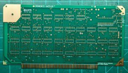
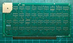
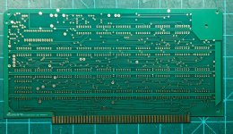
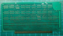
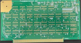
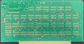
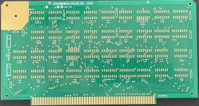
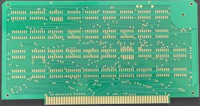
My boards came in today, they turned out really nice.. I'll spend some time this weekend comparing them against Hugo's drawings. These were made from Gary's original gerbers, not his recently revised one.

Board 1 Front:
PXL_20240223_221527974~3.jpg

Board 2 Front:
PXL_20240223_220620398~2.jpg

Board 1 Back:
PXL_20240223_222048243~2.jpg

Board 2 Back:
PXL_20240223_222145615~2.jpg
 
Last edited:
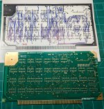
Ok so I printed Hugo's original artwork and am using a sharpie as I go through an verify each trace.
PXL_20240224_001215724~2.jpg

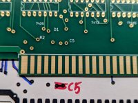
Just finished going through the Top layer of Board 1, only found one issue - there's a leg of C5 which is supposed to connect to a leg of D1 but the trace is missing here.
PXL_20240224_001234264~2.jpg

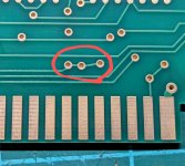
Was just about to post this and I flipped the board over, and there's the trace.. on the bottom layer (and this does match the bottom artwork)..
PXL_20240224_001949956~2.jpg

So I guess there's no problem.. Does this mean the original board had this trace on both the top and bottom?

UPDATE: So far as I can tell, Board 1 Bottom matches Hugo's drawing - no issues found. Onto Board 2.
 
Last edited:
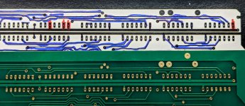
Ok all done with Board 2 - Nothing wrong on the top, and on the bottom - I spotted the same issues that Ansgar found - but nothing more. I think Gary already fixed these in the latest revision/gerbers so I think we're looking pretty good!
PXL_20240224_025048667~2.jpg
 
Just some minor things I can see. For some reason the earth pin has been made into a large hole for the gnd connection of the video output. On mine I used two pcb pins that are 0.9mm diameter and have an associated single socket pin which is for the gnd and video wire . These single socket pins are Jayar parts, but a 2 pin connector would be fine too.

Also, the holes have not been made large enough in diameter (by the look of it) for the ceramic Xtal tuning capacitor (C17) pins. You can drill them out.

Also on the edge connector area there should be a small taper to help it plug in to the socket, not a sharp square edge, but you can always add one by hand. If it is not there high force is required to get the card to plug in and it has a very abrupt entry.

All else looks pretty good.
 
Last edited:
Just some minor things I can see. For some reason the earth pin has been made into a large hole for the gnd connection of the video output. On mine I used two pcb pins that are 0.9mm diameter and have an associated single socket pin which is for the gnd and video wire . These single socket pins are Jayar parts, but a 2 pin connector would be fine too.

Also, the holes have not been made large enough in diameter (by the look of it) for the ceramic Xtal tuning capacitor (C17) pins. You can drill them out.

Also on the edge connector area there should be a small taper to help it plug in to the socket, not a sharp square edge, but you can always add one by hand. If it is not there high force is required to get the card to plug in and it has a very abrupt entry.

All else looks pretty good.

Not sure if you've posted them before and I just missed them, but could you share some hi-res photos of your assembled boards (front & back) thanks!
 
Not sure if you've posted them before and I just missed them, but could you share some hi-res photos of your assembled boards (front & back) thanks!
I will take the photos when I can.

One trick you can do, which is easier than tracing with a pen and comparing each track; you can use a photo of your boards or the artwork that created them, and superimpose that in a drawing program with my artwork .jpg image as a transparency adjust to 50% and color the images differently, red & blue works well and scale them to the same size, I use the vintage drawing program Picture IT, that is also how I drew the artwork. Where the tracks don't overlap, using this transparency method, or are different in any way, you will see just the one color and it becomes very obvious if anywhere, the two patterns are different.
 
We used a similar method, but subtracted one image from the other. I can't remember the exact details now though.

What you are left with is the deltas in the images. Much easier to see...

Dave
 
Hi,

The progress is looking good. I can hardly wait for built-up board photos and final testing showing them working.


.
 
Back
Top