Hugo, in your write up you talked about how the original design probably assigned the right resistor values to the wrong colors. I'm at the point where I need to decide if I use their original resistor assignments, or your updated ones? I don't mind doing the mod - especially if it yields better colors/greyscales. What are your thoughts?
- VCF South West - June 14 - 16, Davidson-Gundy Alumni Center at University of Texas at Dallas
- VCF West - Aug 2 - 3, Computer History Museum, Mountain View, CA
- VCF Midwest - Sept 7 - 8 2024, Schaumburg, IL
- VCF SoCal - Mid February 2025, Location TBD, Southern CA
- VCF East - April 2025, Infoage Museum, Wall NJ
-
Please review our updated Terms and Rules here
You are using an out of date browser. It may not display this or other websites correctly.
You should upgrade or use an alternative browser.
You should upgrade or use an alternative browser.
Cromemco dazzler replica project
- Thread starter Hugo Holden
- Start date
Hugo Holden
Veteran Member
The resistors would need changing but also some tracks too. I decided to leave it as they designed it and regard it as one of the quirks of the original design. It doesn't really matter unless say you were starting with an NTSC color image and processing that to become a Dazzler image, vs say making either a color image or grey scale image from scratch. It is just a compatibility thing, for example if you program what looks like an NTSC test pattern, the luminance levels associated with each color doesn't match NTSC.Hugo, in your write up you talked about how the original design probably assigned the right resistor values to the wrong colors. I'm at the point where I need to decide if I use their original resistor assignments, or your updated ones? I don't mind doing the mod - especially if it yields better colors/greyscales. What are your thoughts?
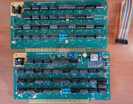
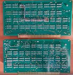
Photos of my boards attached. For the IC sockets which connects the two boards together, I used a blue type. These are a dual wipe design with gold plated contacts that have a very firm grip. At one point I had a lot of these nice sockets, but over the years worked my way through them. Now they seem relatively rare. The other sockets are genuine Augat types, I imported them from the USA for this board rather than using the modern clones. The sockets on the original board I think were the TI type which grab the pin over a small surface area from side to side, I was not keen to replicate those, because I have had a lot of trouble with that type in my SOL-20.
Attachments
Last edited:
Ansgar Kueckes
Member
- Joined
- Feb 11, 2024
- Messages
- 40
Beware of the TI closed frame sockets. It seems that they have been used for the early Dazzler designs. The contacts are 90° turned, so you have a minimum area of touch between the contact and the IC pin. They already have been unreliable in the times the boards have been produced, and quickly were drawn out of the market. Which is one of the reasons they are not available any more. I am using a special version of them in the Apple-1 replica, which is gold plated and works ok (unobtainium by the way). I recommend everyone to use precision, gold plated sockets like the Augat, and you have saved at least half of the testing & fixing efforts. Personally I am planning to use open frame sockets more close to the Rev D originals, but I am slightly masochistic in that point. Don't do that.
Last edited:

This was mentioned earlier in this discussion - the Rev D board (vs the Rev C board that has been reproduced) included a couple of changes mentioned in Appendix A of the Games Manual for Dazzler board 2. This modification consists of a resistor/capacitor circuit added between IC50-12 and IC67-6 (R31 270 ohms and C42 330 pf).Where is C42? I must be blind. I ordered it based on the manual, 330pF - but I can't find it on either board.
View attachment 1274679
Sorry for the poor quality of the scan - but this shows how R31 and C42 are wired between IC50-12 and IC67-6 on Rev D.

Last edited:
daver2
10k Member
Just to give you a little progress report on reverse engineering the source code for the dazzler library (and adding the comments) - it is going well and mostly making sense.
Onwards...
Dave
Onwards...
Dave
") My assembly skills are novice-level at best.
My assembly skills are novice-level at best.daver2
10k Member
Good.
You can interface C with assembler...
Dave
You can interface C with assembler...
Dave
wperko
Experienced Member
- Joined
- Jul 4, 2007
- Messages
- 412
Hi, When the reproduction boards are finalized and working then the software development starts ... I hope somebody can create a dial-up game where two people can either be adversaries in a maze or partners against the computer generated maze and characters ... maybe something like a dial-up CATCHUM or LADDER ... it might be a little slow, but I think it would be a neat step for the S-100 buss systems.
.
.
daver2
10k Member
A multiuser 3D maze would be good.
The maze can be randomised and people placed at random locations in the maze when the game starts.
You then have to escape the maze.
The question then becomes what to do when you see other people, and should there be treasure to collect along the way?
Dave
The maze can be randomised and people placed at random locations in the maze when the game starts.
You then have to escape the maze.
The question then becomes what to do when you see other people, and should there be treasure to collect along the way?
Dave
Another crazy idea I had a few days ago.. TI-calculators for the most part have Z-80s and heck, even Doom has been ported to it. The TI's resolution of 64x96 would easily fit in the Dazzler's mode 2 128x128. There's a huge library of TI games that could potentially be ported..
daver2
10k Member
Doom sounds good!
Dave
Dave
Ansgar Kueckes
Member
- Joined
- Feb 11, 2024
- Messages
- 40
@hmb would be nice to have the full Rev D schematics. There are a couple of other changes on the second board Rev D layout which require check against the schematics (probably mostly changes in the routing), but I couldn' locate the Rev D schematics yet.This was mentioned earlier in this discussion - the Rev D board (vs the Rev C board that has been reproduced) included a couple of changes mentioned in Appendix A of the Games Manual for Dazzler board 2. This modification consists of a resistor/capacitor circuit added between IC50-12 and IC67-6 (R31 270 ohms and C42 330 pf).
Sorry for the poor quality of the scan - but this shows how R31 and C42 are wired between IC50-12 and IC67-6 on Rev D.
View attachment 1274681
Unfortunately the schematic in the scanned copy of the Rev D manual that I have is almost illegible - the small section I reproduced above shows just how bad it is.@hmb would be nice to have the full Rev D schematics. There are a couple of other changes on the second board Rev D layout which require check against the schematics (probably mostly changes in the routing), but I couldn' locate the Rev D schematics yet.
daver2
10k Member
I will check the Cromemco repository tomorrow to see if there is something in there...
Has anyone already checked?
Dave
Has anyone already checked?
Dave
Yes - the Rev D manual copy I have, with the illegible schematic, is from the Cromemco repository.I will check the Cromemco repository tomorrow to see if there is something in there...
Has anyone already checked?
Dave
Last edited:
daver2
10k Member
It was worth asking the question...
Dave
Dave