• Please review our updated Terms and Rules here

XT-IDE Hardware Setup Gallery

Holmes

Experienced Member
Joined
Dec 13, 2010
Messages
313
Location
Marietta, GA
So I am about to get my XT-IDE kits and will soon begin soldering away. I've been searching for any threads where people list their XT-IDE setups. I've seen on the wiki that working hard drives and CF cards are listed, but there's a big gap between this info and what you need to organize your setup. All other info is pretty scattered.

For instance, does anyone have a setup with 2 IDE devices attached (either an HD + CF card reader)? Does anyone have a IDE-to-dual-CF setup and working? Can you put a CF-to-IDE reader with a slot-bracket in the same slot position as the XT-IDE card (is there room physically)? Does anyone have a laptop HD working? If so, with what type of adapter? How have people solved the power problem (supplying your HD or CF with power)?

Those are the types of questions I think would be helpful for those new to this like me. Most of the other threads out there require you to dig through 20 pages of discussion about some very isolated and specific situations, which are obviously very important to those with the issue, but less important to those without that exact setup.

So what I would like is a thread devoted to different XT-IDE setups. Like I said, I think this would be a ton of help to those taking the plunge. Maybe it would give some ideas to those who already have one but didn't think of a certain arrangement.

What to include
---------------
Please include your computer, all hardware components (be as specific as possible), and pictures would be great (ideas about mounting of HDs, etc), in addition to any difficulties you had with your setup. Please don't use this thread as a problem solving/troubleshooting thread. I would also ask that if you need to add to or modify what you wrote, please edit your original post rather than adding a new reply with a comment about a previous posting (to keep the thread from becoming digital kudzu). This will hopefully keep the information more accessible to all. Feel free to ask clarification questions, though.

Anyone else agree? If so, then please post away! I'm excited to see what you guys have done with your XT-IDEs.
 
Last edited:
Setup 1:
IBM PC 5150 B
XT-IDE Card
Dual CF to IDE adapter (attached directly to the IDE header)
Seagate ST1 2.5 GB Microdrive as master
Transcend 128 MB CF card as slave

Setup 2 (without XT-IDE card):
IBM PS/2 Model 30
Sound Blaster 16 with IDE Interface
Network card with XT-IDE bios in its socket
CF to IDE adapter
IBM Microdrive 512 MB plugged in the SB16 IDE

Note: Microdrives only work configured as master.
 
Setup :
IBM PC XT 5160 w/AST SixPack for 640KB total
8087 coprocessor
IBM EGA (256K) and IBM 5154 display
IBM Xebec MFM controller card
Original Seagate ST-412 MFM 10MB
XT-IDE Card
Maxtor 7213AT IDE 213MB
IBM Floppy controller
IBM 5.25 floppy drive

With this setup the XT-IDE menu allows me to boot from either hard drive
(MFM or IDE) or the floppy drive. I also ran the IDE drive controller cable
and one power connector (with extension) through a slot in the back of the case.
This way I can easily attach different IDE drives without opening the case.
 

Attachments

  • DSCF0019.jpg
    DSCF0019.jpg
    91.5 KB · Views: 1
Last edited:
nestor - thanks for answering my dual-CF question, and for showing that microdrives also work.

mikey - I see your IDE cable has capacity for 2 hard drives. Have you connected 2 drives at once successfully, have you had any problems attempting this setup, or have you not attempted this?

Cool stuff. Keep it coming!
 
Last edited:
Leading Edge Model D (IBM XT clone)
Dual floppies
NE1000 Ethernet card
Integrated serial/parallel/FDC/RTC (note: RTC conflicts with default XTIDE IO ports)
Integrated Mono/CGA graphics, set to mono mode
8088 + 8087 coprocessor
XTIDE with 128 MB PQI industrial Flash module, drawing power from IDE header pin 20
MS-DOS 5.0

xtidemod-flash.jpg
 
I've had success using it alone and along the type B IBM/Xebec controller with two 10MB disks attached.

However, at the moment some of the soldering joints has gone loose again, so I will have to resolder once more. I really should try to get myself a soldering iron that actually works...
 
Hey, does anyone have a working setup with one of those IDE-CF adapters that come on an expansion slot bracket so that the CF slot points out the back of the computer?

Something like this:
http://www.psism.com/adcf2.jpg

If so, did you put the XT-IDE in one ISA slot, and then put the IDE-CF adapter bracket in the position for an empty slot (in other words, taking up 2 slots, which I would hate to do), or is there "wiggle room" to fit both in 1 slot?

The above adapter is mounted on the "power supply" side of the bracket (ie. if you mount the bracket in the computer, the side of the bracket closest to the computer power supply). All normal ISA boards are mounted on the "away from power supply" side of the bracket in order to be correctly aligned with the ISA slot on the motherboard. I was hoping that this would allow you to put the above bracket in the same "slot position" as the XT-IDE, as long as your XT-IDE didn't have a bracket. Am I making sense?

Until I have both in front of me, there's no way for me to know for sure, but I'm hoping someone else out there has been through this.
 
I have about 6 machines with XTIDE cards in them, and all of them have a compact flash->IDE adapter as slave devices mounted in the back of the case. IIRC, I did cram both the XTIDE and the CF adapter into 1 slot. Obviously the XTIDE bracket has to come off, but I think all I did was add a little foam separator between the two PCBs and all is good. It's a tight fit for sure, but I believe it's doable.
 
hargle,

Cool. In that case, that's the setup I'm going to try first (with the bracket mounted CF card). I do like the idea of having a hard drive as the master device and the CF as a slave to transfer files, or to use as stable storage (to reduce the wear on the CF card).

I've got several old laptop 1GB hard drives, which I'm probably going to try to use. I didn't see that anyone has a laptop hard drive working with the XT-IDE, although there shouldn't be any trouble, presuming whichever laptop IDE adapter that is used works properly. I'm planning on getting the $1 laptop-IDE-to-desktop-IDE adapters on eBay. I do like the laptop HD route as well because 1) they're smaller and easier to mount, 2) they consume less power, and 3) they're quieter. I am a bit worried about hanging all this extra hardware off the standard 5150 power supply (which is what, 62 watts?).

When I get my XT-IDE built and set up I'll post back here with some pictures as well.

Anyone else have any interesting setups with their XT-IDEs?
 
I wouldn't be too worried about overtaxing the power supply with laptop drives or cf cards, some quick checking tells me that modern laptop drives draw around 2 to 3w on average (one drive I saw checked was as high as 9w, yuck!). The ST-251-1 that's in my 5155 on the other hand is rated 12w typical, up to 36w peak. Considering that 251's have been spinning in various XT's for years now I would think that you should be safe running any pair of half decent laptop drives.

As far as the card itself (XT-IDE) I can't imagine it being any worse than a period disk controller, it's pretty light on it's own physical hardware compared to the WD controller I have paired with said 251, so I would guess that it probably draws less power. At the end of the day it all comes down to whatever else might be installed with it, any lightly loaded system should run without a hitch.

My first plan once I have a card together will be to install it in my 5155 much the same as the image glitch showed above, industrial flash mounted on a card with a simple mod providing 5v from the motherboard, then I'm thinking I'll try to find a second 360k floppy (original style Qume drive if I can find one) to put back in place of the ST-251. I'll take a pic once it's all together and working too.
 
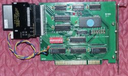
I finally put together the XTIDE. This was a junk-box project--nothing was purchased except for the blank PCB itself. There's a strange mix of logic (LS and HC, depending on what I had on hand) and some ICs (check the LS138 and LS04 at the top of the card) are older than the IBM PC (the LS138 has a 1980 date code; the LS04, 1981.) I also used a AMD Am2764 (circa 1984) EPROM--I don't have any 2864 EEPROM on hand, but I've got scads of EPROMs. The bracket was constructed by bending a piece of sheet metal, drilling and tapping a pair of 4-40 holes for the PCB and riveting the bracket to blank bracket.

So here's a photo.

CGXTIDE.jpg

Note that I replaced the bypass cap C8 with a 3-pin header, with the middle pin removed. C8's actually soldered to the back side of the PCB on the header pins. This lets me take power right from the PCB instead of having to fuss with power cables.

Performance testing was interesting. Even though what's inserted is an ancient (circa 1999) Toshiba 192MB CF card, it substantially outscored a conventional 8GB IDE drive using Norton SI. Looking at the activity LED tells the story--the IDE drive is losing lots of revs, while the CF obviously doesn't have the problem.

Okay, benchmark numbers. With the WD 8GB IDE drive, Norton SI stayed at 1.2, regardless of 4.77MHz or 8MHz turbo mode. With the 192MB CF card, the scores were 1.4 and 2.3, respectively. That tells me that the XTIDE is essentially CPU-bound reading CF drives.

Without going to something like DMA transfer, I think I can hack the card slightly and improve performance by a factor of 2 or more for CF cards.

What it will do with regular IDE drives is anyone's guess. However, it may be possible to fix the IDE drive performance with a software interleave--the down side is that you won't be able to read the drive in anything but an XTIDE that's been set up the same way as the original.

However, I'll need to make software patches to the XTIDE BIOS also. Right now, I'd like a simple one that's easy to deal with; not the general-purpose-do-everything-for-everybody IDE Universal BIOS. Hargle, do you have the source to the old BIOS kicking around? I suppose that I could write one of my own, but that would be a lot of useless wasted effort.
 
Hi Chuck! Please try swapping the address lines around. You may be able to get the IO ports to become adjacent (LOHI) and then be able to use better software transfer methods.

We are working on a new and improved Dual DMA IDE board for the N8VEM project. I am not sure when this will be done but hopefully soon. Unfortunately as a result of the ice storm last week the family internet connection is still severely degraded so that is messing things up for the next few days.

Thanks and have a nice day!

Andrew Lynch
 
Hi Andrew,

Thanks, that's what I'll try first. My hope is that the parts to the original not be altered or changed. This would also be easily manageable with the CPLD version by simple reprogramming of the CPLD.

--Chuck
 
I finally put together the XTIDE. This was a junk-box project--nothing was purchased except for the blank PCB itself. There's a strange mix of logic (LS and HC, depending on what I had on hand) and some ICs (check the LS138 and LS04 at the top of the card) are older than the IBM PC (the LS138 has a 1980 date code; the LS04, 1981.) I also used a AMD Am2764 (circa 1984) EPROM

That was a question that I had as well, Can I mix HC/HCT and LS logic interchangeably, as long as the pinout is the same? Will there be any ill effects? The thought of pulling some of this stuff off of some old cards I have laying about appeals to my thrifty Scotch-Irish side. (read cheap SOB)
 
That was a question that I had as well, Can I mix HC/HCT and LS logic interchangeably, as long as the pinout is the same? Will there be any ill effects? The thought of pulling some of this stuff off of some old cards I have laying about appeals to my thrifty Scotch-Irish side. (read cheap SOB)

Of course you can mix HCT and LS families--that's one of the reasons that HCT exists. Mixing HC can get a little iffy depending on the circui. The big issue is that an HC logic "high" input level is about 3.5V, while an LS and HCT logic "high" input level is about 2.0V. So, if your're driving a bunch of inputs from the same line, HC may not work--but you can get around that by adding a pullup to the HC input.

HC logic works over a wide range of power supply levels; in particular, it's happy as can be at 3.3V, while the same is not true of HCT or LS.

Fortunately, the XTIDE design is fairly conservative, so HC/HCT/LS logic should work just fine. I had some Fairchild 74F573s (somewhat akin to 74ALS logic) and even they worked fine, even if their speed was overkill for the application.

LSTTL family logic really is obsolete; HC and to some extent, HCT logic should be the target for new designs.
 
Hey Andrew,

I think I may have a simpler modification--simply swap A0 and A3 on everything but the PROM. This makes the I/O port addressing a little strange, but it gets the job done. For example, if you're using a base address of 300H, the address of low-order byte of the data register would be 300H, the high-order 301H, the error register would be 308H; the sector count, 302H, the sector number, 30AH, and so on.

So we'd still get the right low-byte/high-byte pairing at consecutive addresses for the data register.

I've got to look at the PCB to see if there's an easy way to do the swap...
 
Hi Chuck! Well try it and see if it works! Nothing sells a good idea like a working prototype!

I don't think a LOHI IO port arrangement is enough by itself to support DMA but it would be a good start and simplify the driver I think.

Thanks and have a nice day!

Andrew Lynch
 
Hi Andrew,

No, LO-HI isn't enough to support DMA. but I have other ideas for that, in case the PIO is still too slow.

The basic idea is that to read a sector, you currently use the following code, entering with CX=256 for a 512 byte sector:

Code:
readLoop:
                in      al, dx                  ; get lower half
                mov     ah, al
                or      dx, 8                   ; switch to 2nd data reg
                in      al, dx
                and     dx, NOT 8               ; switch back
                xchg    ah, al
                stosw                           ; save it
                loop    readLoop

Which amounts to 8 instructions and 17 instruction bytes per word. If you shuffle the ports around a bit, as I described, then the code to read a 512 byte sector becomes something like this, entering with CX=128:

Code:
MoreData: 
       in      ax,dx
        stosw           ; read and store a word
        in      ax,dx
        stosw           ; word 2
        in      ax,dx
        stosw           ; word 3
        in      ax, dx
        stosw          ; word 4
        loop    MoreData

Which transfers 4 words in 9 instructions (10 instruction bytes) by letting the 8088's BIU do the byte shuffling work. My guess is that this will be at least 2-3 times faster.

At any rate, Hargle's sent me his code and I've re-assembled it and burned it so at least I know that it works. Now to stare at PCB traces and get the old X-acto knife out...
 
UPDATE 2/13/11 I swapped A0 and A3 and modified Hargle's BIOS slightly by changing the I/O port definitions and then substituting the PIO code detailed above. On boot, the code correctly identifies the IDE drive, but won't do sector I/O it (fails with a timeout). The fact that the drive information from the IDENTIFY command is being read correctly is a good sign, however.

Looking at the BIOS code, there are some fixups needed--to fix the use of stuff like this:

Code:
                mov     dx, cs:[settings.ioBasePort]     ; data register
                add     dx, IDE_SECTOR_COUNT_REG
                mov     al, cl                  ; sectopr count
                out     dx, al                  ; # of sectors to work on
                inc     dx                      ; LBA low
                pop     ax

                out     dx, ax                  ; out LBA low+mid
                add     dx, 2
                mov     al, bl
                out     dx, al                  ; LBA high

                inc     dx
                in      al, dx
                and     al, SLAVE               ; keep device #
                or      al, LBA
                and     bh, 0fh
                or      al, bh
                out     dx, al                  ; out device + upper LBA

                inc     dx                      ; command reg
                mov     al, ch
                out     dx, al

With the new code, doing INC and constant arithmetic on the port number is a no-no! (it's not good coding practice anyway). Symbolic port references only (they're not consecutive any more)! So, hopefully, after I've located and fixed all of those, it'll take off and work.
 
Okay, what the heck, just after midnight, nothing on the one-eyed monster (who the heck actually looks at the Grammy awards, anyway?), so I figured I'd take a stab at the code.

Success.

With the new code, the Norton 4.5 SI numbers stack up this way:

8GB Maxtor 91531U3 IDE drive: CPU: 4.77MHz SI =1.0 Disk SI = 6.3
8GB Maxtor 91531U3 IDE drive: CPU: 8.00MHz SI =1.7 Disk SI = 6.4

192MB Toshiba CF card: CPU: 4.77MHz SI=1.0 Disk SI = 6.1
192MB Toshiba CF card: CPU: 8.00MHz SI=1.0 Disk SI = 6.3

That's close to a 6x improvement on the disk and 4-5 on the CF.

I don't think CPU speed is a factor any longer at least for these devices. And I suspect that DMA would actually be slower.

The mod was pretty simple--I cut the A0 and A3 traces at each via (near the edge connector) on the wiring side of the PCB and just ran two wires soldered from said vias to the appropriate 74LS138 pins.

The swap shouldn't matter with the ROM unless you're using an externally-programmed EPROM like me. In that case, use the following C program to swap the bytes around in the BIOS image file before programming:

Code:
#include <stdio.h>
#include <stdlib.h>
#include <string.h>

#define K_TO_SHUFFLE 8

#define BYTES_TO_SHUFFLE (K_TO_SHUFFLE * 1024)	// self-explanatory

//  Program to shuffle data addressed by interchange A0 and A3 lines.
//  -----------------------------------------------------------------
//
//    Done originally for the XTIDE modifications, but may find some
//    other application.
//
//    Re-arranges bytes such that:
//
//	0123456789abcdef -> 082a4c6e193b5d7f
//
//    Chuck Guzis, February, 2011.
//

void main( int argc, char *argv[])
{

  FILE
    *in,
    *out;				// input and output FDs

  unsigned char
    image[ BYTES_TO_SHUFFLE],		// shuffler
    temp;				// temporary byte

  int
    i, j, k;				// scratch integers


  printf( "\nROM A0-A3 swap data shuffler (%dKiB version)\n", K_TO_SHUFFLE);
  if ( argc != 3)
  {
    fprintf( stderr, "\nCommand syntax is %s <input-file> <output-file>\n",
      argv[0]);
    exit(-1);				// quit after giving summary
  } // if improper number of arguments

  in = fopen( argv[1], "rb");
  if ( !in)
  {
    fprintf( stderr, "\nERROR - Could not open input file %s\n", argv[1]);
    exit(1);
  } // if input won't open

  out = fopen( argv[2], "wb");
  if ( !in)
  {
    fprintf( stderr, "\nERROR - could not open output file %s\n", argv[2]);
    exit(2);
  } // if output won't open

  memset( image, 0, BYTES_TO_SHUFFLE);	// clear buffer
  k = fread( image, sizeof( unsigned char), BYTES_TO_SHUFFLE, in);
  if ( k != BYTES_TO_SHUFFLE)
    fprintf( stderr, "\nWAarning - Short read; buffer padded with zero.\n");
  fclose( in);

//  Do the shuffle.

  for ( i = 0; i < BYTES_TO_SHUFFLE; i += 16)
  {
    for ( j = 1; j < 8; j +=2)
    {
      temp = image[ i+j];
      image[i + j] = image[ i+j+7];
      image[i+j+7] = temp;		// swap 4 pairs of bytes
    } // swap odd-numbered bytes

  } // shuffle in 16-byte blocks

  k = fwrite( image, sizeof( unsigned char), BYTES_TO_SHUFFLE, out);
  fclose( out);

  if ( k != BYTES_TO_SHUFFLE)
  {
    fprintf( stderr, "\nError - Write error; only %d of %d bytes written\n.",
      k, BYTES_TO_SHUFFLE);
    exit(10);
  } // if short write

  printf( "\nAll done.\n");
  exit(0);

}  // end of main

Enjoy!

P.S. Attached are the "un-swapped" and "swapped" BIOS images that I used.
 

Attachments

  • MXTIDE1.ZIP
    6.2 KB · Views: 1
Last edited:
Back
Top