Clint
Experienced Member
Being new here I thought I would write up this week’s Vintage Computing Endeavours.
Last week I purchased a tired old 3032 and a 8050 dual disk drive over the internet and on Wednesday I completed a nice round trip the The Centre for Computing History in Cambridge UK to pick it up. My intension is to electronically refurbish the computer and add it to my small but growing collection of 1970's Computers. I had good memories of the iconic looking machine from my teens; I owned a PET 8032 you see when I was about 17, given to me from my brothers company - one of many they threw out at the time.
I must say I was very impressed with what the Centre for Computing History are doing up there in Cambridge, the place looks great and run by people with pure passion. If you have not already, go and take a 'peek' at their website: http://www.computinghistory.org.uk/
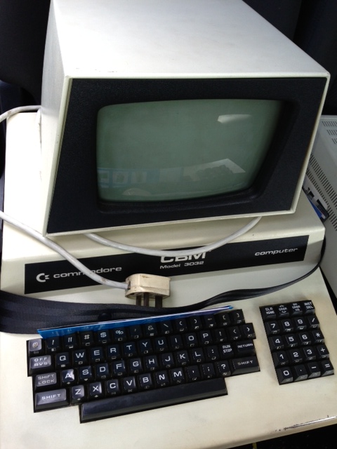
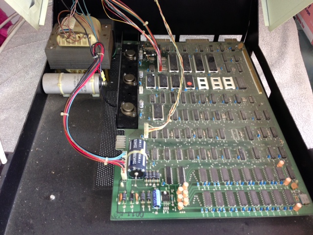
My New PET with its Seatbelt on:
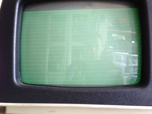
Thursday morning I set about fixing it, I have recently been quite ill, so rather than disappear into my workshop I was allowed to throw a towel over the dining table and fettle with the 70's technology in comfort. This unit was purchased with no display other than scan lines when the brightness was turned up.
Poorly - Scan lines:
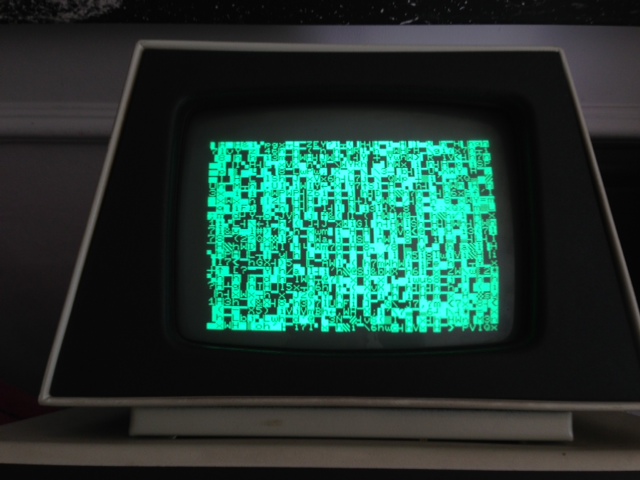
So first thing I decided to do was a voltage check, I picked the cathode side of each diode that sat across each regulator, with voltages correct and present I also checked for the same readings on the main memory chips, again all voltages were correct. One thing I remember with my 8032 was its start-up beep, so on not hearing this on my new PET I assumed the Logic board was not working, anyway while scratching my head I decided to turn down the brightness to rid the screen of the scan lines, as I pulled on the brightness control on the rear of the CRT, the screen flickered into life with a load of garbled characters!
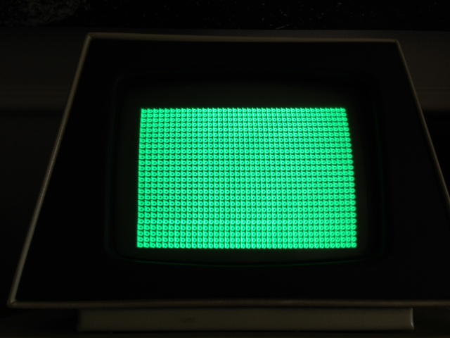
Garbish:
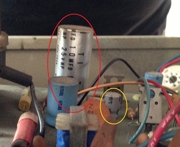
So the logic was working albeit with some sort of memory issue, my 'focus' turned to the CRT side of things, I stripped the circuit board out leaving the deflection wires connected and noticed a couple of out of shape capacitors. So my first job was to replace as many as I could with what I had in stock, I carry most values in 105 degree 50v, I manage to replace all but 2, a 10MFD 25V non polarised and a 3.3uF 200v Electrolytic; both of which I have since mail ordered. Most of the removed capacitors were reading quite high; for instance all of the 47uF were reading 64uF +- 2uF!
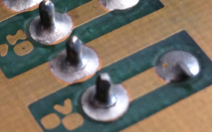
While I had the board out, I lifted the two heatsinked semiconductors up, cleaned the hardened compound off and put some new modern thermal grease under them. I then decided to reflow all solder joints and found the original problem:
Dry Joint:
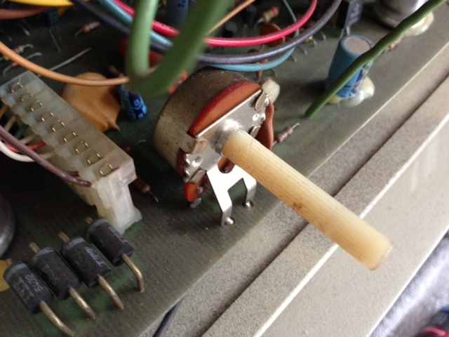
With all the joints now like new I cleaned the rest of the board, serviced both variable resistors with electronic contact cleaner and then placed some silicon grease around the HV cup and replaced the whole assembly. Once switched back on I was presented with a nice stable image that did not budge with any movement of the brightness pot.... result")
Brightness Pot, very near the dry jointed connector:
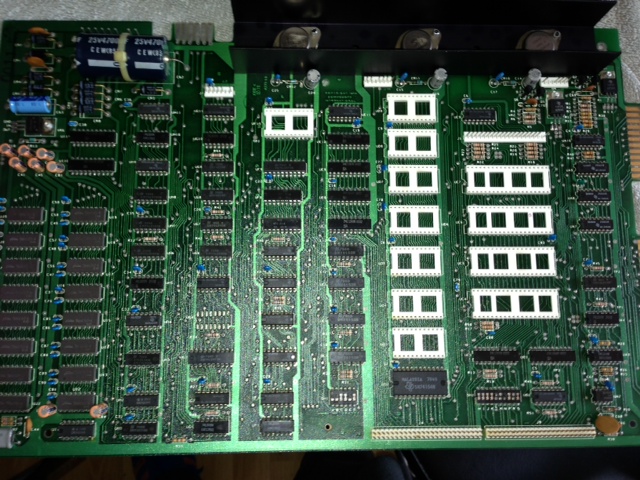
However I still had that garbled screen to contend with, I decided to give the Logic board a good clean, a soapy hot water brush off and a good hairdryering after ; much nicer to work on that way:
Before and After:
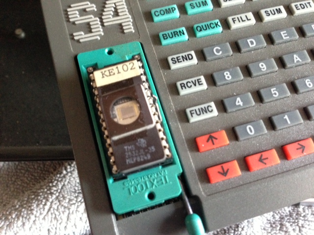
This made no difference to operation, so with some searching on this forum I found the pet tester image and blew that onto a TMS2532, installed and booted it told me what I needed to know, the CPU was running fine but ALL the memory was bad.....
ROM Burning and the PET TESTER Memory diagnosis:
Now I am seasoned enough to realise that not all the memory would be shot and knew I was more probably looking at some sort of bus or addressing issue.
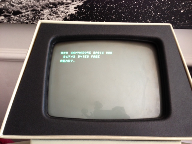
With that in mind I decided to refit the original Kernel ROM and remove the remaining socketed chips one by one, I was obviously having one of them lucky days, I removed the left hand PIA, and boom no more garbage, presented to me now was pure nostalgia…….. a BASIC prompt, however the feeling of the 'fix' was short lived as I had no cursor.
So Nearly, BASIC with no cursor:
I went on to remove the second PIA and rebooted, wow, I now had a cursor, I found this very odd could 2 PIA's be faulty? I tried both of the 6820's in each socket and for sure they both had problems, one stopped the kernel from loading keeping the initialisation rubbish on the screen and one hung the BASIC cursor, no matter which socket they were in each presented the same error. I had a look through my chip boxes and found 2 6821 PIA's which are now at home in my repaired PET. (I am sure the 6821 is 100% backward compliant in place of the 6820)
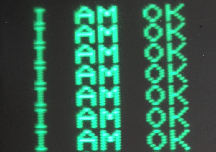
The PET Speaks:
All in all I had a great day, as did my kids, by around 2pm I had my boys arguing over whose turn it was to ‘have a go’, and my eldest son spent 2 hours working with PRINT and INPUT commands which he had never used before.
Anyway I hope you like my story, my next steps are to replace the final 2 capacitors on the CRT board, replace all the capacitors on the logic board and find a cable so I can start to work on decommissioning dual floppy drive.
Happy days
For Reference the PCB Part Number is: 320350 REV2
Last week I purchased a tired old 3032 and a 8050 dual disk drive over the internet and on Wednesday I completed a nice round trip the The Centre for Computing History in Cambridge UK to pick it up. My intension is to electronically refurbish the computer and add it to my small but growing collection of 1970's Computers. I had good memories of the iconic looking machine from my teens; I owned a PET 8032 you see when I was about 17, given to me from my brothers company - one of many they threw out at the time.
I must say I was very impressed with what the Centre for Computing History are doing up there in Cambridge, the place looks great and run by people with pure passion. If you have not already, go and take a 'peek' at their website: http://www.computinghistory.org.uk/
My New PET with its Seatbelt on:
Thursday morning I set about fixing it, I have recently been quite ill, so rather than disappear into my workshop I was allowed to throw a towel over the dining table and fettle with the 70's technology in comfort. This unit was purchased with no display other than scan lines when the brightness was turned up.
Poorly - Scan lines:
So first thing I decided to do was a voltage check, I picked the cathode side of each diode that sat across each regulator, with voltages correct and present I also checked for the same readings on the main memory chips, again all voltages were correct. One thing I remember with my 8032 was its start-up beep, so on not hearing this on my new PET I assumed the Logic board was not working, anyway while scratching my head I decided to turn down the brightness to rid the screen of the scan lines, as I pulled on the brightness control on the rear of the CRT, the screen flickered into life with a load of garbled characters!
Garbish:
So the logic was working albeit with some sort of memory issue, my 'focus' turned to the CRT side of things, I stripped the circuit board out leaving the deflection wires connected and noticed a couple of out of shape capacitors. So my first job was to replace as many as I could with what I had in stock, I carry most values in 105 degree 50v, I manage to replace all but 2, a 10MFD 25V non polarised and a 3.3uF 200v Electrolytic; both of which I have since mail ordered. Most of the removed capacitors were reading quite high; for instance all of the 47uF were reading 64uF +- 2uF!
While I had the board out, I lifted the two heatsinked semiconductors up, cleaned the hardened compound off and put some new modern thermal grease under them. I then decided to reflow all solder joints and found the original problem:
Dry Joint:
With all the joints now like new I cleaned the rest of the board, serviced both variable resistors with electronic contact cleaner and then placed some silicon grease around the HV cup and replaced the whole assembly. Once switched back on I was presented with a nice stable image that did not budge with any movement of the brightness pot.... result
Brightness Pot, very near the dry jointed connector:
However I still had that garbled screen to contend with, I decided to give the Logic board a good clean, a soapy hot water brush off and a good hairdryering after ; much nicer to work on that way:
Before and After:
This made no difference to operation, so with some searching on this forum I found the pet tester image and blew that onto a TMS2532, installed and booted it told me what I needed to know, the CPU was running fine but ALL the memory was bad.....
ROM Burning and the PET TESTER Memory diagnosis:
Now I am seasoned enough to realise that not all the memory would be shot and knew I was more probably looking at some sort of bus or addressing issue.
With that in mind I decided to refit the original Kernel ROM and remove the remaining socketed chips one by one, I was obviously having one of them lucky days, I removed the left hand PIA, and boom no more garbage, presented to me now was pure nostalgia…….. a BASIC prompt, however the feeling of the 'fix' was short lived as I had no cursor.
So Nearly, BASIC with no cursor:
I went on to remove the second PIA and rebooted, wow, I now had a cursor, I found this very odd could 2 PIA's be faulty? I tried both of the 6820's in each socket and for sure they both had problems, one stopped the kernel from loading keeping the initialisation rubbish on the screen and one hung the BASIC cursor, no matter which socket they were in each presented the same error. I had a look through my chip boxes and found 2 6821 PIA's which are now at home in my repaired PET. (I am sure the 6821 is 100% backward compliant in place of the 6820)
The PET Speaks:
All in all I had a great day, as did my kids, by around 2pm I had my boys arguing over whose turn it was to ‘have a go’, and my eldest son spent 2 hours working with PRINT and INPUT commands which he had never used before.
Anyway I hope you like my story, my next steps are to replace the final 2 capacitors on the CRT board, replace all the capacitors on the logic board and find a cable so I can start to work on decommissioning dual floppy drive.
Happy days
For Reference the PCB Part Number is: 320350 REV2
Last edited:
.JPG)
.JPG)
.JPG)