• Please review our updated Terms and Rules here

Pdp 11/45

Hi All;
As far as I can tell the SAP and SSR boards are OK, I put in Core Memory and I load address 000000 and I try Examine and the ADRS ERR Led comes on, So I need to find out what Causes an ADRS ERR.. I have also tried the Deposit and it is the same.. When I depress REG DEP I can get the Address to increment, but NOT when I depress REG EXAM.. Also, when doing a REG DEP I doesn't show anything when I flip up some of the Switch Register Switches.. I need to look into all of this, like read a basic Front Panel operation manual, before I make too many assumptions..
THANK YOU Marty
 
Hi All;
I have found a couple of things, I have two address bits that are intermittent from the switch register.. I don't know yet If it is a Cable issue or a Switch issue.. And so that is the first thing I need to get resolved..
I am also not sure How to test my Core Memory and know for sure that it is truely being accessed, not to say anything about good or bad bits.. Since when I try to read from the M9312 BootStrap Terminator Card, and I get the same Address Error Led coming on.. It still might be a Unibus Issue..
So, after all I think I need to build the UA Unibus Analyzer to find out whether the UniBus is working or not.. And that is my second/ next Project..
In the maintenance Manual, it says the ADRS ERR is caused by one of 5 things..
A. Odd Address Error
B. Fatal Stack Violation
C. Non-Existent Memory Addressed
D. Parity Error
E. Memory Management

THANK YOU Marty
 
Hi All;
Al, Thank You for reminding me of that.. I though Either No one really Cared or wasn't willing to post anything that I could use or would be of interest, or help..
The only thing is that I need to find another place for the Core Memory Power Supply, So I can Tip the BackPlane on its side, so I have access to the Backplane Pins, and so then hook up the Logic Analyzer.. I guess I could Use the Grabber Hooks and hook them from the top side, On the BootStrap Terminator Board..
After I figure Out HOW to make the Logic Analyzer Work !! They are SOOOO Much Trouble getting Set up, before I get anything out of them..
I can try to hook up the Analyzer from the Top of the machine..
THANK YOU Marty
Are you sure the memory board is strapped to being at location zero? Or at least within the
memory limits of where you are trying to address? Is your stuck bit gone now? Bit 15?
 
Tip the BackPlane on its side, so I have access to the Backplane Pins, and so then hook up the Logic Analyzer
After I figure Out HOW to make the Logic Analyzer Work !! They are SOOOO Much Trouble getting Set up, before I get anything out of them..
I can try to hook up the Analyzer from the Top of the machine..
THANK YOU Marty

If you're probing the Unibus, take one of your unused wirewrap cards and make a card to attach the logic analyzer probes on.
Then, plug that into an unused Unibus slot. It sounds like the wood frame is enough of a hassle to manipulate that you probably
don't want to be flipping things around much.

The model of analyzer you have has a floppy disk, which can save the settings. Set it up and save the settings, then you never
have to mess with setup again for Unibus probing.
 
Hi All;
AL,
""If you're probing the Unibus, take one of your unused wirewrap cards and make a card to attach the logic analyzer probes on.
Then, plug that into an unused Unibus slot."" Excellent Idea, THANKS !! Yeah, The only one I have is the one I was going to build the UA on..
THANK YOU Marty
 
Hi All;
Al, Thank You for reminding me of that.. I though Either No one really Cared or wasn't willing to post anything that I could use or would be of interest, or help..
The only thing is that I need to find another place for the Core Memory Power Supply, So I can Tip the BackPlane on its side, so I have access to the Backplane Pins, and so then hook up the Logic Analyzer.. I guess I could Use the Grabber Hooks and hook them from the top side, On the BootStrap Terminator Board..
After I figure Out HOW to make the Logic Analyzer Work !! They are SOOOO Much Trouble getting Set up, before I get anything out of them..
I can try to hook up the Analyzer from the Top of the machine..
THANK YOU Marty

I have the HP1664A which is almost identical to the one that you have. What do you want to do? State or timing analysis? I.e. do you have a clock signal that strobes data into the analyser or is it supposed to gather data free running? Go ahead and ask, I might be able to help you with it!

When analysing the CPU while executing code I mostly used state analysis where the probes were attached to the Address and Data bus, clock signals attached to MSYN and SSYN. In state analysis the LA collects data until it triggers and then until the buffer is full. When I had a problem that the machine halted I just set the LA for for a trigger that never would arrive. Then when the machine halted I pressed stopped and then I had all the last memory transactions in the LA.

When understanding the interrupt problem or strange problems in the TU60 I used timing analysis. Again triggering is crucial. I have found edge triggering useful. Setting up the signal that initiates everything as the trigger and then look at the waveforms.

When the LA starts up it will arrive at the configuration menu. Navigate to the "Type" field and select either "Timing" or "State". Then press FORMAT button and add signal labels to the probes. In state analysis make sure that you set up the clock signals in the format menu. If timing analysis then I advice to set up some trigger in the trigger menu. (press TRIGGER button)
Now it is ready to run. Hit the RUN button and see what pops up on the screen. Go back modify your setup and run again.

And as Al mentioned, save the config on the floppy disk so you just can recall it later on.
 
Hi All;
I will be gone for about the next 3 hours, but when I come back, I can try and get the logic Analyzer going.. I know how to Turn it on, but that is about all I know about this particular machine.. When I get back I will turn it on and start asking questions..
Traddle, Yes bit 15 is fixed.. but, I have bits 12 and 7 to work out, since they are intermittent at some of the time, at least bit 7 is, and I need to find if it is a cable problem or one of the Boards, I can switch out the Data Board, and if I get bit 12 back, then its the Data Paths board, if not then the PDR board, that is if it is not Front Panel, nor Cable.. and do the same with bit 7..
I think I do have the Memory strapped for "zero", but when I get back I will check it for sure..
Also, I have an MF 11-UP Backplane and I have only one side with 16K of Core, Do I need to full Both the Front and the Back, so I have 32K of Core to make it work ??
THANK YOU Marty
 
Last edited:
Hi All;
I will be gone for about the next 3 hours, but when I come back, I can try and get the logic Analyzer going.. I know how to Turn it on, but that is about all I know about this particular machine.. When I get back I will turn it on and start asking questions..
Shoot! I need to understand what kind of measurement you are up to. Please tell me in detail.
 
Hi All;
MatisLind, I don't know that I can tell You in detail, as I don't exactly know myself..
But, what I am trying to determine is IF or WHY the memory is not working, that is, - Why can't I Examine or Deposite to or from memory.. Is it a CPU Board Problem or Is it a Memory Board problem ?? At this point I do not know.. I guess, first is see with my Scope If I have MSYN since you mention that I would/could use it as a clock signal.. Once I determine that then I can start looking at other signals with the Logic Analyzer..
I need to look at the Flows for Examine and Deposit and determine what the CPU and the Micro-Code is doing and expected to do, when I depress the switch for either one..
But before even that I need to find out what is going on with bits 7 and 12..
THANK YOU Marty
 
I guess, first is see with my Scope If I have MSYN since you mention that I would/could use it as a clock signal

That only works if the processor is running. You need either a digital storage scope or a logic analyzer if you have a single-shot event, like one memory
access from a front panel read or write.
 
Hi All;
AL, Thank You for the information..
I am having a funny thing happen, (but not funny to me), I put the PDR card on my Extender Card, and Yes, the signal comes thru from the Switch, But it also shows up on the Led when I do a Load Address.. I am going to try it back in place WithOut the Extender and see If it is just a Card Pin connection that might have been dirty.. I don't want to have to hang a scope probe on it, E54 a 74S153 just to make it work..
THANK YOU Marty
 
Hi All;
MatisLind, I don't know that I can tell You in detail, as I don't exactly know myself..
But, what I am trying to determine is IF or WHY the memory is not working, that is, - Why can't I Examine or Deposite to or from memory.. Is it a CPU Board Problem or Is it a Memory Board problem ?? At this point I do not know.. I guess, first is see with my Scope If I have MSYN since you mention that I would/could use it as a clock signal.. Once I determine that then I can start looking at other signals with the Logic Analyzer..
I need to look at the Flows for Examine and Deposit and determine what the CPU and the Micro-Code is doing and expected to do, when I depress the switch for either one..
But before even that I need to find out what is going on with bits 7 and 12..
THANK YOU Marty
What about wiring up the LA with the MSYN and SSYN signals (I guess that these signals will be generated by the front panel logic or is the front panel controlled by the CPU macrocode? I don't know much about the 11/45, but the KY11-LB used for 11/34 and 11/04 is kind of stand-alone unibus exerciser) and the address bus to start with. Use timing analysis in the LA. Select timing analysis in the configuration menu. The LA uses arrow keys and SELECT and DONE buttons mostly.
Press FORMAT to set up the signals that you are analyzing. Use up down arrows and SELECT button to configure a signal. Then use arrows to to find a specific probe signal to select for this logical signal. It is possible configure the address buss with many signals in both state and timing mode. Use the TRIGGER menu to set up trigger on MSYN signal. The trigger menu is a little bit tricky. Use arrows and press SELECT on (1). Then goto (a) and press select it and then change it to "edge1". Press done to escape out of these menus. Then finally go down and set the conditions for "edge1" and on what signal it applies. Probably it would be useful to have a falling edge triggering. If this doesn't work put one probe on the examine / deposit signals from the front panel and trigger based on that. And then trace the signal to where it produces the bus control signals.

But if it is the case that microcode is involved in the front panel operation then you need the check all signal related to the microcode including the master clock before testing anything else.

Good Luck!
 
Hi All;
MattisLind, THANK YOU for the information on the Logic Analyzer.. As soon as I get these other issues out of the way, I will try it and see what I get..
I got bit 12 to work with the PDR Board back in place with out the Extender, but now I have bits 1 and 4,5,6 always on.. I have pulled the Boards from the PDR up to the Data Paths, and will clean and Re-insert them in place, and see if that makes any difference.. I had traced both bits from the Front Panel thru the Cable so that seems to be fine, even though bit 7 is now acting up and bit 12 is OK..
THANK YOU Marty
 
Hi All;
I cleaned the Boards and I traded the RAC Board, (M8103) for another one, it is an (M8123), which the print set for set up says can be used in a -D, the Proms are the Same Printed Code on the Top of the Prom.. AnyWay it now seems to be all better as far as Misc bits turning on when I do a Load Address.. Things look stable now.. Now to copy MattisLind's advice for the Logic Analyzer, and see IF I can make any sense of it.. THANK YOU MattisLind !!
THANK YOU Marty
 
Hi All;
While, copying and trying to make sense of everything.. I have TWO Questions --
1. Does Anyone have the code that is used in the M9312, for the Console Emulator with Diagnostics, at address 165020.. All I would need are about the first 6 or so lines of code, in other words the first six lines of Binary.. I have found a way to read something, but I don't know if what I am reading is correct or just a bunch of misc binary numbers..
2. When reading the manual for the MF 11-UP Memory, (Last night) which is what I have.. I noticed that it stated that I should set the Voltage for +20 volts, at the regulator to +25 volts, So IS my not being able to read from Memory that my voltage is TOO LOW, and that it should be +25 volts instead of my current +21 volts ?? By Turning it up to +25, I don't want to FRY anything..
THANK YOU Marty
 
Hi All;
While, copying and trying to make sense of everything.. I have TWO Questions --
1. Does Anyone have the code that is used in the M9312, for the Console Emulator with Diagnostics, at address 165020.. All I would need are about the first 6 or so lines of code, in other words the first six lines of Binary.. I have found a way to read something, but I don't know if what I am reading is correct or just a bunch of misc binary numbers..
Dan North has put a lot of M9312 files here
 
Hi All;
MattisLind, Thank You for the link, I compared and it is not the same.. Between the listing and what the computer shows.. Could be anything..
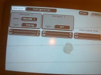
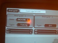
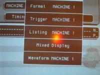
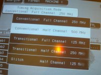
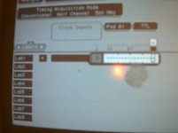
Here are some pictures of the Logic Analyzer, before I get confused and/or not sure what to do.. The pictures are not that great !!
I have another problem, I have to figure out where to put the Logic Analyzer, when I stand it up on the floor, the Pod Cables are Not long enough to reach the PDP 11/45.. If I put the HP under the PDP 11/45, the weight of the Computer would crush the HP.. And IF I put the HP on top of the PDP 11/45 it would break some cards.. It looks like I need to build something for the top of the computer to hold the HP..

01232014958.jpg 01232014963.jpg 01232014960.jpg

01232014961.jpg 01232014964.jpg

THANK YOU Marty
 
Last edited:
Hi All;
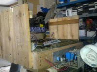
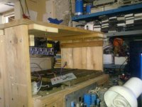
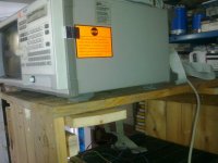
I had to go on an errand this morning, but after that I finished the shelf to hold the HP Logic Analyzer on top of the PDP 11/45 frame..
So, here are some pictures, If you happen to see any screws hanging down from the top they for now are to hold the top shelf together.. After I try it for a few days and make sure I like what I have built, I will take out the wooden screws and replace them with screws and washers and nuts.. Something more permanent..

01242014965.jpg 01242014966.jpg 01242014967.jpg

THANK YOU Marty
 
Back
Top