• Please review our updated Terms and Rules here

CT-1024 Terminal Manual?

falter

Veteran Member
Joined
Jan 22, 2011
Messages
6,580
Location
Vancouver, BC
I think this one will be directed at Chuck mostly.. Chuck do you know if there was an operation manual for the ct-1024? I've looked all over Matt Holleys site.. he has assembly instructions that give a bit of info on starting the unit up for testing.. but not much else. I'm trying to figure out how to run it in just tv typewriter modr.. to see if the keyboard works. Im getting replacement capacitors.. and i dont think the serial board is working.. but there is a switch that brings up a page of ? marks and I seem to recall reading *somewhere* that there was a keystroke or button or something that prepared the unit for typing. I just want to see the extent of functionality if I can.

One other question... off one of the leads from the power supply I'm getting 12.95v.. is that likely tied into the old capacitor issue? I'm hoping i've ordered the right replacements. All the originals were measured in mfd.. had tobuse a calculator to try and figure out the uf equivalents.
 
As far as I know 68mf = 68mfd = 68uf

When I started in ham radio in the late 50's caps were commonly shown and labeled as mfd rather than the newer uf symbol.
 
Nope, as far as I remember, you turned it on and hooked it up. The most helpful part of the manual was the schematic for me.

Jumper (RxD and TxD and you should be in local mode.
 
I tried that but didn't get anywhere. I'm guessing most of my problems are in the power supply. I temporarily removed the serial board and plugged the keyboard into the port on the motherboard itself, but that achieved nothing either, except when I was playing with the voltages I briefly got it to come up to a field of Ns, and if I hit a key it changed them to whichever key I pressed.

Hoping I get those caps soon and that that helps my problem out a bit. I'm having trouble finding the big 5000uf 10v one though.. all I can find thus far are 'axial'.
 
The standard PSU for the CT1024 was pretty awful. I rebuilt it from scratch--the TVT draws a lot of power for which the original PSU was woefully under-designed. Today, you can get a pre-made power supply to do the same thing for not much money.
 
I kind of thought about getting an external psu.. so as not to take away from the original unit (I'm thinking I could just connect it temporarily when I want to use it). But I'm intimidated by that kind of thing.. no idea what to buy.
 
There's no particular reason that it has to be screw terminal. In the days of "brute force" linear DC supplies "Computerlytic" caps were very common. Nowadays with switching supplies, they're somewhat uncommon. I suspect a "snap-in" radial cap would do just fine.

At any rate, I found my manual for the P197 PSU used for the CT-1024. The ratings stated are +5V, 2.25A, -5V, 20 ma, and -12V, 60ma. So a pretty limp-wristed supply. FWIW, the RS-232 outputs are also pretty limp-wristed at +/- 4.75V. A 3-ourput PSU with those ratings should be pretty simple to find.
 
Oh, good heavens no! Nothing that fancy (although a good bench supply can be useful :) )

Even a small (mini ITX) PC power supply should do. Or use one of the surplus ones that seem to be wandering around. Did you ever find a good surplus store in BC? Otherwise, there's Jameco.
 
Last edited:
Oh, good heavens no! Nothing that fancy (although a good bench supply can be useful :) )

Even a small (mini ITX) PC power supply should do. Or use one of the surplus ones that seem to be wandering around. Did you ever find a good surplus store in BC? Otherwise, there's Jameco.

Yes I was considering Jameco. I think the problem is the supply your own power supply thing predates me and I feel really nervous about getting the wrong thing. I'm concerned about making sure the amperages work, etc. I understand they can be more than you require but not less?
 
Falter,

Yep, that power supply should do - with the proviso that the three outputs are isolated from each other and ground. I found some additional documentation at http://www.electroindustries.net/specifications.php#2555A which seems to state that is the case.

I would connect as follows:

Set the switch to INDEPENDENT (so that you can adjust the A and B voltages separately).

Set the 'A' side for 5V.
Set the 'B' side for 12V

Join the + side of the 'A' supply to the + side of the 'B' supply to the - side of the fixed 5V supply. This is your common 0V lead. Also connect to GND post.

The - side of the 'A' supply is now your -5V supply.
The - side of the 'B' supply is now your -12V supply.
The + side of the fixed 5V supply is your +5V supply.

The fixed +5V supply is capable of delivering 3A (which is greater than the 2.25A that Chuck has identified). The 'A" and 'B' supplies are each capable of delivering up to 0.5A (which is greater than the 20mA and 60mA that Chuck has identified).

I would, however, check the voltages with a multimeter before connecting them to you CT-1024 just to be sure you have wired everything correctly. Connect the -Ve lead of your multimeter to the common 0V lead from the power supply (GND) - and measure each voltage from the outputs separately. 'A' should indicate -5V, 'B' should indicate -12V and the fixed supply should indicate +5V.

I am looking for a new bench supply - that one looks good apart from the cost of shipping and import duty to the UK (and the seller states that they only ship to the States and Canada).

Dave
 
Thanks muchly Dave! Your detail is exactly what I need being new to bench power supplies, etc. So when you say 'join', you mean literally there will be wires linking all four terminals ( A +, B +, 5v -, gnd)?

Another question.. do I need to remove the old power supply completely, or could I just clip my leads to the voltage outputs on its pcb?

Falter,

Yep, that power supply should do - with the proviso that the three outputs are isolated from each other and ground. I found some additional documentation at http://www.electroindustries.net/specifications.php#2555A which seems to state that is the case.

I would connect as follows:

Set the switch to INDEPENDENT (so that you can adjust the A and B voltages separately).

Set the 'A' side for 5V.
Set the 'B' side for 12V

Join the + side of the 'A' supply to the + side of the 'B' supply to the - side of the fixed 5V supply. This is your common 0V lead. Also connect to GND post.

The - side of the 'A' supply is now your -5V supply.
The - side of the 'B' supply is now your -12V supply.
The + side of the fixed 5V supply is your +5V supply.

The fixed +5V supply is capable of delivering 3A (which is greater than the 2.25A that Chuck has identified). The 'A" and 'B' supplies are each capable of delivering up to 0.5A (which is greater than the 20mA and 60mA that Chuck has identified).

I would, however, check the voltages with a multimeter before connecting them to you CT-1024 just to be sure you have wired everything correctly. Connect the -Ve lead of your multimeter to the common 0V lead from the power supply (GND) - and measure each voltage from the outputs separately. 'A' should indicate -5V, 'B' should indicate -12V and the fixed supply should indicate +5V.

I am looking for a new bench supply - that one looks good apart from the cost of shipping and import duty to the UK (and the seller states that they only ship to the States and Canada).

Dave
 
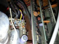
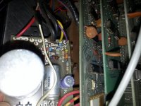
Okay.. so I have the original psu out a bit:

20140927_105148.jpg

20140927_105137.jpg

So if I understand correctly, I can attach the pins for 5v, -5v etc of the AT psu by wire to the appropriate terminals on this old power supply (I am reluctant to desolder it). The only thinga that throw me are where the ground wires connect up (they appear to be a fairly heavy gauge) and that white wire that is soldered in beside one of the resistors.
 
Sorry, your illustrations don't show where the other end of the white wire goes. I suppose I could check my assembly instructions, if it's not possible to show that.

EDIT

Forget it--that white wire is the 60Hz reference from the transformer secondary--not shown on the schematic--nominally 6.3VAC.

Foo--it might be simpler just to refurb and beef up your current supply. The big problem is the TO-220 MJE3055 transistor. It needs to pass a higher current than the package and heatsink is rated for. Perhaps using a TO-3 2N3055 on a substantial heatsink might work better. Replacing the electrolytic capacitors probably wouldn't hurt either.
 
Last edited:
Yeah. I had a feeling this wasn't going to be that easy. And I am being *very* cautious.. this is the oldest piece in my collection (all the chips date to 75) so I don't want to make things worse, and I'm also keen to keep it as close to original as possible.

And you're fairly confident we're chasing the right suspect here with PSU right? The original problem was video like this:

https://www.youtube.com/watch?v=2WQRCQiXRcE

And no response from keyboard. I'm still looking at the docs to figure out what the switches do.. there is one that switches between that field of question marks and nothing. There's also that very brief line of garbage characters at the beginning. I've wondered if part of this has to do with the monitors I'm using vs. what they were expecting you to connect this to back in the day..
 
Back
Top