• Please review our updated Terms and Rules here

PDP 11/45, Part 5

Hope you feel better soon, Marty!

I don't think I could have gotten far with my CPU without a working KM11. I think you'll find it quite worth it if you can get yours working!

It also occurred to me this morning that 005000 and 001000 differ by just a single bit. We might want to try some different values in location 1000 as an easy test to make sure we are actually looking at an incorrect load and not some individual stuck bits?

Cheers,
--FritzM.
 
I tried to get over to the RICM when I was on holiday over in the States last year - but that fell on 'deaf ears' with the rest of the family. No dad/husband (delete as applicable) we are not being dragged around a computer museum whilst we are on holiday...Dave

Our museum is mostly a not so nice warehouse and some very nice office (Lab) space. Your family might have liked what we have on display in the Lab, but only a true enthusiast would like the warehouse.
 
Hi All;

Dave, no Brandy, but I do have DayQuil/NyQuil (Generic)..

FritzM, "" It also occurred to me this morning that 005000 and 001000 differ by just a single bit. We might want to try some different values in location 1000 as an easy test to make sure we are actually looking at an incorrect load and not some individual stuck bits? ""

A Very Good Point !! Thank You, I will check it out and Let everyone know..

OK, I put '000240 into the next two Addresses ('001000 and '001002) before I put in Dave's program, and bit 11 is Not on..
But, I also don't think it is really running Dave's program, not like I saw last night or when ever..
So, I need to do two things when I am better, One is get my KM11 going and two change to core to run the Program in, so, I can run it right away and take the time to enter it.. (Before it goes BAD )..

OK, I put the Altered equivalent of Dave's program into Core..
And Now after it goes Bad,
I press Load Address with the switches set to '001000 and it shows '001000 on the address leds..
I press the Examine switch and for a slight moment, a flicker the Data Leds show '000240, before they go to all '000000..
then the Address leds change to '000240..
I can do this over and over and it does the same thing..
I think we have been here before..
Mr. Greens Evil Twin..

I Just had a thought, what is the same between these two it's the clock, Something is going out or is not right on the Timing Board, would be my best guess !!

THANK YOU Marty
 
Last edited:
So we know the issue isn't data value related or just a single bit fault.

The TIG card is always a possibility. Personally, I try to find what is actually causing the observable symptom and then work back from that to find the root cause.

Beware though - as I have mentioned above. The first time you see the data on the front panel LEDs it is NOT coming directly from the DR register (where the data should be latched to ultimately) - but from the BR register. The next time you see it (or don't in your case) it should have been coming from the DR register. So my hypothesis is that the data didn't get latched into the DR register but the SR (address) register by mistake.

I would (personally) have a look at the clock line on the SR register to identify why the data value is getting latched into the SR register itself. This will be your 'clue' and then work back to find out why microcode signal SRK is being operated (during an EXAMINE). The SR register should't be modified in an EXAMINE following a LOAD ADDRESS. So you will have to keep depressing LOAD ADDRESS and then EXAMINE to try and catch the gremlin in the act. If you accidentally hit two EXAMINEs in succession the EXAMINE STEP microcode will be invoked which will cause SR to have two added to it before performing the examine. You don't want this to happen whilst you are looking for why SR is being modified.

Good hunting...

Dave
 
Hi All;

Dave, Thank You for the hypothesis of what I need to hunt for..

"" The TIG card is always a possibility. Personally, I try to find what is actually causing the observable symptom and then work back from that to find the root cause. ""

OK..

I need to look at the Block Diagrams and see which Board has the SR Register as well as the DR Register..

I am asking, not stating, "" So my hypothesis is that the data didn't get latched into the DR register but the SR (address) register by mistake. ""
Could this be a MUX, that is choosing the SR instead of the DR ??

No, I have just looked, and there is no common MUX..

"" I would (personally) have a look at the clock line on the SR register to identify why the data value is getting latched into the SR register itself. This will be your 'clue' and then work back to find out why microcode signal SRK is being operated (during an EXAMINE). ""

I have not found a clock for these Registers, either SR or DR.. But, It could be that I am just not seeing it and it is right there staring me in the face..

I have been reading KB-11 Maintenance Manual and trying to follow what does what, and what goes to where.. I am in chapter 5, section 5.3.1 and 5.3.2 and 5.3.3..

I tore the place apart looking for the two Timing Boards that I know that I have somewhere..
They are not to be found, but found some other things that I have been looking for, for about 6 months, so not a total loss..
When I am not looking for them, they will show up..
Not a minute after I wrote the above, I went around the corner of the stuff shelves, and on top of the Drives were the Boards I have been looking for for a few days now.. The Light was just right or the angle of my looking was just right and there they were..


THANK YOU Marty
 
Last edited:
Hey Marty,

Sorry for the late reply - I have been out most of the day. Finished for the day now - so catching up with our mega thread...

The SR and DR registers are both on the M8101 - check drawing GRAD.

SR<0:5> is E59 (I think). Pin 9 is the clock input which comes from E21 pin 6. E21 pins 3 & 4 have the SRK signal from the microcode. E21 pin 5 has the T1 clock from the TIG.

DR<0:3> is E62. The clock is on pin 11 and the DRK bits (x2) from the microcode arrive on pins 9 and 10.

With a probe on SR clock (E21 pin 6) you should get a pulse when you depress "LOAD ADDRESS" and no pulse when you depress "EXAMINE". If you get no pulse at this time - I have a wrong hypotheses... If you do get a pulse when you hit EXAMINE, you need to look at E21 pin 3 and see what the SRK signal from the microcode is doing. It shouldn't change state during an EXAMINE.

Just remember to operate LOAD ADDRESS and then EXAMINE and don't hit EXAMINE twice in succession (otherwise you will get a pulse on E21 pin 6 as a result of incrementing the address before fetching the next data word from memory).

Hope there is enough here for you?

Dave
 
Last edited:
Hi All;

Dave Thank You..
"" Hope there is enough here for you? ""
Plenty.. And I am going to give it a try and Report what I find back to You, and everyone..

"" SR<0:5> is E51 (I think). Pin 9 is the clock input which comes from E21 pin 6. E21 pins 3 & 4 have the SRK signal from the microcode. E21 pin 5 has the T1 clock from the TIG. ""

It's E59, my copy is easy to read.. I will take a look at it, now..

I have found 'a' problem, the clock on pin 5 of E21 is about 600 to 700 millivolts.. Not something like 3 volts..
Now I need to make sure its NOT my Extender Card..

I checked T3 on the GRA Board, and it's normal 3 thru 4 volts, so, I will Put the Extender on the TIG (Timing ) card, and see what that shows..
Looks like a False alarm, I went back and checked the timing Board and it was OK, so I Re-Extended the GRA Board and the Timing signal is Now OK..
While on the Extender, it does not fail, (so far), but, it doesn't run either..
I am going to try FritzM's program, and see..
I have loaded Fritzm's Program, and it doesn't run either..
I have checked both the SR and DR, and for now they both work..
So, I think my best Next step is to get the Maintenance Card (KM-11) working..

I have discovered something that might be a clue
I am making sure of my Switch connections first..
Putting the computer in R/C mode, I find that I can vary the frequency from about 6.5 MHZ to about 36 MHZ..
When I have it running at about 11 MHZ about one third of normal speed and about as low as I can go for the Core to Work
With the Timing Board on it's Extender, I can make it show the Error described above, where it copies the Data to the Address..
But, when I switch it to normal speed, it works fine.. I am going to take the Timing board off of the Extender.. and try this again..
I still need to find out why the Led's are not displaying the correct micro address..

Next, I need to find where the Micro Address are generated that are displayed on the Led's..

I have made a change to the Timing Board, I Socketed E35 (74S140) and to pin 8 of that IC, I can inject any frequency that I want to from my osc, divide down circuit and at really Low frequencies I can see my Micro-address Leds change numbers.. When it is set to RC Mode, I now can go lower than 1 Hz.. And next week I will need to find where these are coming from and make sure I have good connections and so getting the correct values..

THANK YOU Marty
 
Last edited:
"Next, I need to find where the Micro Address are generated that are displayed on the Led's.."

The connector carrying the console data display is shown on drawing PDRH.

The data display MUX is on drawing PDRF.

The eight (8) microcode address lines are "RACD RAR00 H" to "RACD RAR07 H" and come from drawing RACD.

Bits <0:5> are latched by E86. Bit <6> is latched by part of E109 and bit <7> is latched by part of E88.

Note (however) that there are multiple latches for the address lines for the ROMs. I guess this is because one latch will not have the fan-out to drive a load of ROM devices? As a result - different ROM devices appear to have different latches for their address lines. So, there could be a failure mode where the microcode address indicated on the console data LEDs is correct - but part of the microcode ROM array is getting an incorrect address due to its address latch failing. That would cause a corrupt microcode word to be presented to the subsequent logic. Something to bear in mind when debugging (what you see is sometimes not what you get)...

Dave
 
Hi All;

Dave Thanks for the Information..

"" Note (however) that there are multiple latches for the address lines for the ROMs. I guess this is because one latch will not have the fan-out to drive a load of ROM devices? As a result - different ROM devices appear to have different latches for their address lines. So, there could be a failure mode where the microcode address indicated on the console data LEDs is correct - but part of the microcode ROM array is getting an incorrect address due to its address latch failing. That would cause a corrupt microcode word to be presented to the subsequent logic. Something to bear in mind when debugging (what you see is sometimes not what you get)... ""

This actually makes sense.. I will make an Ohm check for these bits, and let You know what they show at present..

THANK YOU Marty
 
"This actually makes sense.. I will make an Ohm check for these bits, and let You know what they show at present.."

Checking with an Ohm meter will not tell you anything about the state of a marginal SN74XXX latch (which is potentially what the fault is). You need to 'catch it in the act'.

Dave
 
Hi All;

Dave, Thank You for Your concern.. But, You misunderstood what I am trying to do..

The Ohm check is to make sure who connects to whom and what to where.. Not to check the state of the IC..
I just want to know for sure that the KM11 is connected to where we think it is connected to on the PDR Board AND OR on the RAC Board..
As there are two sets of Leds each going to a different set of signals.. I want to know which set is connected to which IC..

THANK YOU Marty
 
Hi All;

Well I have Not found where the 'BSR 00' and the 'ISR00' signals go to on the KM 11, but I do know that on RACD RAR00 (ED2) is connected to PDRF (AB1)..
Hopefully I can find out where they are connected..

I have found the four switch settings that go to the timing Board, and I have all of the Pin numbers for the KM11 Labeled in my NoteBook..

I just had a thought, (This morning..) I don't know why I didn't think of it sooner..
I can plug my Tester into each of the main slots, numbers 6 thru 12 and use my Digital Pulser on the different KM11 connections to find out who connects to who.. My Led's on the Tester will blink if I have a connection..
It would be alot easier than hit and miss I have been trying to do with the Ohm Meter..

So far the Connections on the UBC Board don't make sense, So I went and Verified what I have on the Timing Board (slot 15) to make sure I was counting in the correct direction.. Which I was, in my Diagram/Listing..

Timing Board Slot 15

KM11 TIM Signal
FB2, FB1, XXMA S1
FV2, FV2, XXMA S2
FA1, FJ1, XXMA S3
FU1, FU2.. XXMA S4..

UBC Board Slot 12

KM11 UBC KM11 Sig, UBC Sig,
FD2, BA1, BSR14, SSYN Mat,
FE2, EU2, BSR1, Cont Ok Mat,
FJ2, FH2, BSR8, Parity Err Mat,
FM2, FR1, ISR1, MSYN B Mat,
FR2, EN1.. BSR0, Bust Mat..

TMC Board slot 11

KM11 TMC KM11 Sig TMC Sig
FH1, DC1, BSR3, AERF Mat,
FL2, DE2, BSR7, SERF Mat,
FP2, DL2.. ISR2, PS04 Mat..

No PDR Board Signals..

RAC Board Slot 9

KM11 RAC KM11 Sig RAC Sig
FT2, CF2.. B MSYN, FP REQ..

IR Board Slot 8

KM11 IR KM11 Sig IR Sig
FD1, FE1, C (1) H, MAT ZH,
FE1, FL1, ISR7, MAT C H,
FM1, FF1, ISR8, MAT V H,
FU2, FR1.. B SSYN, MAT N H..

No GRA Board Slot 7 Signals

No DAT Board Slot 6 Signals..

After further research, I found, where the KM11 file came from..
NOW I UnderStand Why the names Don't make sense , they are the Signal Names for the PDP 11/05 and NOT for the PDP 11/45 !!!
I need the PDP 11/45 KM11 Overlay to Put the correct names to the different Signals..
I Found the Names for the 11/40 Overlay, I don't know how close they are to what I have.. No, they don't seem to match either..

I found a Conversion OverLay for the PDP 11/45..

Timing Board Slot 15

KM11 TIM Signal
FB2, FB1, XXMA S1
FV2, FV2, XXMA S2
FA1, FJ1, XXMA S3
FU1, FU2.. XXMA S4..

UBC Board Slot 12

KM11 UBC KM11 Sig, UBC Sig,
FD2, BA1, SSYN, SSYN Mat,
FE2, EU2, CONT OK, Cont Ok Mat,
FJ2, FH2, PAR ERR, Parity Err Mat,
FM2, FR1, MSYN, MSYN B Mat,
FR2, EN1.. BUST, Bust Mat..

TMC Board slot 11

KM11 TMC KM11 Sig TMC Sig
FH1, DC1, AERF, AERF Mat,
FL2, DE2, SEF, SERF Mat,
FP2, DL2.. T, PS04 Mat..

No PDR Board Signals..

RAC Board Slot 9

KM11 RAC KM11 Sig RAC Sig
FT2, CF2.. B FP REQ, FP REQ..

IR Board Slot 8

KM11 IR KM11 Sig IR Sig
FD1, FE1, Z, MAT Z H,
FE1, FL1, C, MAT C H,
FM1, FF1, V, MAT V H,
FU2, FR1.. N, MAT N H..

No GRA Board Slot 7 Signals

No DAT Board Slot 6 Signals..

I still have to find the others Signals..
I can Now tell that the KM11 Board that I wired up, was for the PDP 11/40 and so it makes No sense on the PDP 11/45..
I think I am going to need to wire up a new one, that is Just for the 11/45..
Looking at my Douglas Boards, I can Cut one Down..
Which I have now done..

I also see my Mistake, or Mis-thinking after thinking about it..
I thought that the same kind of Signals were being Displayed as what I had been seeing when I used this before in (most likely) the 11/40..
So, when looking at what I had on my Led's it showed '021 and '444 Octal, which (I thought) represented my Microcode and either pre or post microcode..
But, they Represented things that were completely different, than what they did on the 11/40, which led to my confusion..
And so I thought something was Wrong with my Micro-code, even though the U/ADRS CPU on the Front Panel Switch was showing the correct value..

I have put the Machine Back together and it is doing the same thing as before.. So, nothing more got broke..

THANK YOU Marty
 
Last edited:
Hi All;

Dave, Thanks for Your concern..

I have that link, in fact that is where is got what information I needed to get the correct Overlay..

"" The KM11 is the same for all machines - ""

Yes, normally You would be right.. But, since this one was built different using numerical Indicators, it would not have been easy to try and find and figure out what it meant when it showed something on it's Display.. Since it was different than a normal KM11..
The One I am building is more Like a normal KM11..
And If He Takes PayPal I will most likely just go ahead and get one from Him..

THANK YOU Marty
 
Hopefully he does take PayPal - because I am in the process of ordering 2 * KM11 and 1 * UA11 blank PCBs from him an anticipation of solving problems with my 11/45 cards (I am trying to get ahead of the game). Looking to purchase some extenders from Douglas Electronics also.

Dave
 
Hi All;

Dave, Thank You for Your reply..
Yes, I was thinking of one of each myself, since I don't need two KM11's and the UA11 might be of some help as well.. Since We haven't gotten down to the Root of the problem as of Yet..
I have sent an Email asking about PayPal..
I got a Response From Guy at ShireSoft, and He didn't say NO on the PayPal..
Yes, He Takes Paypal, I just Submitted my Order..
He says He only has the KM11 in BareBoard and the Plastic Overlays..

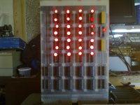
Here is my New current KM11 Testing all of the Led's, No Signals have been attached..

002.jpg

While checking out the Signals as I get them attached, I noticed that T5 is not doing anything, T1 thru T4 are fine and quite active..
Now I don't know If T5 is supposed to be active or not at this point, But, after I get all of the KM11 wired I can do some more looking around..

I found a Culprit, an open Resistor R139 (1K)..

I also found another anomaly, When I run it in normal mode, I cannot get T5 to do anything, BUT,
When I am in R/C Mode with my Oscillator then I have T5 Working, So something is preventing T5 from working while in Standard mode, I need to trace out the difference.. Tomorrow..
Also, I am noticing that after I press either Address Load or Examine it goes to Micro-address '270 and I think it needs or should be '230..
So that should be looked at as well..

I tried a different Board, my M8123 and it shows the correct addresses when trying to do a Load Address or an Examine..
So, That points to the M8103 as having that Problem.. It still will not run Fritzm's chaser program..
But, it does seem to Run at address '000000 either instruction of '005007 or '000777..

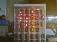
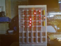
Here is a Picture just after I turn it on and then the next Picture is after a Reset.. And all of the signals are attached to it..

003.jpg 005.jpg

THANK YOU Marty
 
Last edited:
Hi All;

What I need is to make a Board that has one of the Light Chaser Programs in Diode Array or Some Kind Of Prom, but not being a prom, but would be Prom like..
That No matter What speed I would Run the machine at it would still be able to Read it and Execute its code or Program..
I do have a small Diode Matrix Board, but I don't think it is large enough to hold about 8 to 10 instructions..
I would be willing to make something on a Douglas Prototype Board..

I know I would need some 74174's or 7474's and tie their input High or low..
And some 7442's or 74150's for address selection, along with some 7430's or something like that..
What I don't know is "How" to make it do a read.. What signals are needed, etc..

I know I could use a few Eproms, But Would they still work at the Extremely slow speeds that I would be using to "Trace Out" what the Various Boards are doing ??

Any Ideas ?? Suggestions ??

I found some more things out, (clues), I had thought before that since it was stopping at the about the Second address in the program, that the problem might be that the Trap Board was not decoding the '177560 address correctly..
But I have put into Core, starting at address '000200 the Basic Address Test Up program..
And it goes into (Deposited) Core and is Examined just fine, So it's doesn't seem to be Addressing..
But, when I try to Run it, it stops at what looks like Address '000002, and will not go beyond that point..
Also when I put either '000777 or '005007 into address '000000.. And Run it, I don't know if it is running correctly or not..
I Don't know when a properly running 11/45 Executes either one of these Instructions what the Address and Data Led's are Supposed to show..
Mine show 'No Address Led's' on and in the Data Led's only bit '000002 (Octal) is lit..

This afternoon, I have been working on trying to get Both of my M8109 Timing Boards to work, Comparing them to each other and looking for differences and or problems..


THANK YOU Marty
 
Last edited:
Hi All;

I was doing some light reading before going to bed last night..
And, I ran across a sentence that IF it would be true would make sense as to what or why the 11/45 is not working..

The sentence basically said that T5 is used to Clock PCA..
Now if my Timing board is not generating T5, then what is in it, when it starts up will maybe allow it to run one Instruction and then hang..
I just now had a thought, what might be Wrong with this synopsis is that, do I need the PCA when I do an Examine or a Deposit ??
So I need to hang a wire on the clock of the PCA IC and see if it is getting any clocking during a Run, as well as a Deposit or an Examine..

Ok, It does not use PCA with Examine or Deposit..

And when I run a Program there is NO T5, But when I do a 'Reset' I get a pulse from T5.. The KM11 shows it stopping on T1 after I press 'Start',
So, I can make a modification of my Last statement and look up in the Maintenance Manual as to what blocks T1 from Continuing..
As the Manual says that it Basically is a Ring Counter and it should just keep on counting, and it isn't..

1. Not in T4 or T5.. Possibly a bad IC, a 74S11 most likely.. I will need to check this out.. Not the IC I was thinking of, but this is OK..
2. Semiconductor Memory Delay.. I need to check this out..
3. Conventional Memory Delay.. I need to check this out..
4. Operating System Test.. I have had problems with this before, If it is NOT Insulated well enough it will show a Low and stop the Machine, so it is worth checking out.. This is OK as well..
Also, I need to check out both 74S65's E13 and E20, since they are wire-ORed..


THANK YOU Marty
 
Last edited:
Back
Top