• Please review our updated Terms and Rules here

PDP 11/45, Part 5

+100 for your post fritzm. A lot of excellent information condensed into a nice short post.

Marty, before reverse engineering the entire universe in your notepad - can I suggest you read http://bitsavers.informatik.uni-stuttgart.de/pdf/dec/pdp11/1145/EK-KB11A-MM-004_Aug76.pdf. That manual contains a very good description of the operation of the microcode logic for the 11/45 at both a high and detailed level and would serve as a very useful 'primer' before delving into the innards...

Dave
 
Hi All;

Dave, Thank You for the Link..

The one I have printed out, is the older one for KB-11A, where as Your Link is for KB-11A & D..
So, I will need to find out the difference between the two volumes..

As, I don't have some of the Beginning pages for Flows and Block Diagrams.. I will need to use Your previous link for that..
I am copying down in my NoteBook, the MicroWords bit placement and definitions, before going much further..
And I will need to copy or get a copy of the Block diagrams, especially on the ROM Definitions page, before going much further..
So I can follow who goes to whom..

THANK YOU Marty
 
Hi Marty - hope you are feeling a bit better today.

After having a look back at your post #65 where you describe your interesting (and repeatable) phenomenon with the LOAD ADDRESS and EXAMINE console commands I have a proposal of where to look first.

The LOAD ADDRESS microcode stores the 'address' you want to look at in the SR register (which also appears on the BR bus for display on the address LED's on the console).

The FIRST time you press examine - the microcode at EXM.10 (microcode word 070) should be executed. The address (stored in SR) should still be presented on the ADDRESS lamps and the data itself (at the specified address) should be stored in register DR (and displayed on the console data lamps via a parallel route via register BR). If this works (and in your example you said it did as 5000 was displayed) then let us assume that everything is OK here for now.

The NEXT time you press examine - the microcode that gets executed is EXM.00 (at microcode word 071). Question - does this word get executed? To find out the answer to this question you will have to seriously slow down the CPU clock - or use your maintenance card to single step (or even single cycle) the microcode. Set the front panel switch to display the microcode address. The microcode addresses should go something like 170, 167, 170, 167, <PRESS EXAMINE>, 071, 070, 153, 134, 230, 170, 167, 170, 167... If the microcode at word 071 was executed - this is good news. If not we need to look further as to why. FYI microcode word 071 increments the address stored in the SR register. If data is getting mixed up with the address this microcode word is a possibility for error.

Looking at word 071 in detail it appears to select the SR register as the 'A' input to the ALU (AMX=2); select the SR register to be displayed on the console address lamps (BAX=2); set the shifter for NO SHIFT (SHF=2); Select a constant of +2 to be fed to the BMUX (KMX=1); select the ALU to perform the operation A PLUS B (ALU=3) load the result from the ALU (sent via the shifter and the SRMUX) into the SR (SRK=1). The 'B' input to the ALU is set to select KOMX (BMX=0 as default), and SRMX is set to select the output from the shifter as input to the SR register (SRX=0 as default).

As you say that the address changes to 5000 and never increments - but the first EXAMINE seemed to work right - what I am assuming is that either microcode word 071 is not being executed, or it is but it is going wrong.

What I can't seem to see at the moment is how the last data value of 5000 (which should be stored in BR & DR is transferred to SR without having +2 added to it by invoking a single fault (the most likely scenario). AMX could erroneously have a value of 0 instead of 2 (selecting DR instead of SR) - but +2 should be added to the data value of 5000 and stored in the address register in this case (which is not happening).

Having just looked at the block diagram I wonder if DR is being selected by the BAX signal instead of SR to be sent to the console address lamps (and used as a virtual address)? BAX would then have to have the value 0 (to select DR) as opposed to 2 (to select SR). I would also have to invoke the fault that the transfer of SR to BA in microcode words 170 and 167 (CON.00 and CON.01) is also going wrong - but that is the same fault I am proposing anyhow. That fits the bill - one fault accounting for the problem. I wonder if I can simplify the above brain dump into a simple series of manual operations or where to look?

Possibly just looking at the MUX selector signals for the the MUX supplying the virtual address on drawings DAPS, C, D) after the address has 'flipped' to 5000? The SR input to the MUX should have the correct address and the DR input to the MUX should have the data. If this MUX is letting through the DR (data) to the address lines by mistake...

But I am going to have to leave that as an exercise for you tonight whilst I get some sleep :). Fritzm - what do you think?

Dave
 
Last edited:
Hi All;

Dave, all I can say is that the above is an amazing piece of fabulous work !!

I am still a bit hazy, I am having trouble reading things at present.. BUT,
I will try to re-read it and Understand completely what all You are saying..
I think I sort of Understand what You are saying and it Sounds correct or right, in my fizzled mind..
This definitely will need to go into the NoteBook..

I will need to see about slowing down the clock and following each statement through it's logic, as You are describing it to me..

Fritzm, Yes, I would like to hear from You and Your thoughts..

THANK YOU Marty
 
Hi guys,

First, regarding KB11-A,D maint vs. KB11-A maint -- I usually prefer to work from the older, KB11-A-only version. Since I don't have a KB11-D, I don't need to worry about the differences between the two. :) I find the older KB11-A-only manual a little more compact and easier to read.

Regarding Dave's post on the microcode, yes, this is exactly the kind of reasoning I used to work through the bugs in my CPU. One comment here: when the flow diagram lists both (170) and (167) above the CON.00 state, it does *not* mean that microaddresses 170 and 167 will be fetched in sequence. Rather, it means that the exact same microword is stored at both of those microaddresses. It's just one box on the flow because the machine will behave exactly the same (and go to the same successor microstates) regardless of which of the listed addresses was fetched. The reason there are redundancies like this in the micro control ROM has to do with how the micro-branch logic works -- you can't just branch to an arbitrary microaddress, so sometimes you have to give the state you want to branch to a duplicate entry at one of the possible branch destinations you do have available. The control flow fits together like a bit of a jigsaw puzzle this way :)

The upshot if this is that when the console is idling, you'd expect to see microaddresses 170, 170, 170, 170... and not 170, 167, 170, 167...

Regarding Dave's fault scenario -- there's a lot to digest there :) I need to think it through a bit more before I can comment. If I get some time in front of my machine later, I'll throw in the KM11 and record some of the microaddresses and light sequences I see walking through Dave's case.

cheers!
--FritzM.
 
So, I read through Dave's fault proposal and I agree, definitely worth checking!

I would put the DAP out on an extender, put in the KM11, do the LOAD ADDRESS and the first EXAMINE, then switch to single microstate mode on the KM11, hit EXAMINE again, step with the KM11 until stopped at T2 in state 071. On a working 11/45, address lights should show 1000 and DATA PATHS should show 1002. If Dave's suggestion of BAMX fault is true, then address lights would show 5000 here instead.

If you see 5000 then there's a strong indication of a BAMX failure. I'd then give a look at E38 on the DAP, which implements bits 10 and 11 of the BAMX (described on engineering diagram DAPC).
 
The RICM has two 11/45 systems both with KB11-A/KT11-C that each misbehave in different ways. This level of sophistication in debugging makes me wonder it I have the talent required to ever get one of these systems running. Maybe I should just stick to PDP-8 systems. ;-)
 
Hi All;

Fritzm, Thank You for all of You hard gathered information, and Your much needed Suggestions..
Please, Run the fault proposal with a Good Machine, and also with Pressing the Load Address and Pressing the Examine switch..
And at each Micro-Code what You find and what the machine shows..
That way I can compare What You see against what I see.. Both on the Front Panel and on the KM11..

M-Thompson, "" The RICM has two 11/45 systems both with KB11-A/KT11-C that each misbehave in different ways. This level of sophistication in debugging makes me wonder it I have the talent required to ever get one of these systems running. ""
Don't put Yourself so low, I wish I had Your Talents that You use on your PDP 8, both when I was debugging my 8i clone and my 11/45..
And You have two Systems, which means You have twice as many Boards as I do or more, to get a system working..

THANK YOU Marty
 
Hi Marty, I did just verify with my machine:

Deposit 005000 to location 001000, HALT and then START while HALT (this does a RESET). LOAD ADDRESS 001000 and EXAMINE (shows 1000 on address lights, and 5000 on DATA PATHS). Put KM11 in single microinstruction mode, put data display on uADDRs, hit EXAMINE once more, then step with KM11 stepper switch until lower 7 bits of data display show 071, you will be halted in T2.

On my machine, address lights show 1000, BUS REGISTER shows 1000, DATA PATHS shows 1002. If Dave's theory is right, you would see 5000 in your address lights here instead. In any case, let us know what you see in address lights, DATA PATHS, and BUS REGISTER in this state.

Cheers,
--FritzM.
 
Last edited:
Hi All;

First of all, I will need to re-trace my wiring out and see what and where I have my Switches wired on my KM11..
And then make sure the Led's are correct as well..
On the KM11 the led's show '021 and '444 octal, so I know I need to check it out..

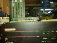
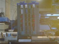
001.jpg 003.jpg


I have tried the operation like Fritzm did above, and I noticed something that I hadn't seen before..

I Deposited '005000 into Location '001000 and then did the Start, halt thing..
It didn't take long for the error to appear, only a couple of tries..
I press Load Address with the switches set to '001000 and it shows '001000 on the address leds..
I press the Examine switch and for a slight moment, a flicker the Data Leds show '005000, before they go to all '000000..
then the Address leds change to '005000..
I can do this over and over and it does the same thing..

While trying to do fritzm's thing when it works data paths show, '001000 address and '005000, data, buss register shows '001000 and display register '000000..
When it is broke data paths shows address '005000, data '000000, bus register '000000 and display '000000..

THANK YOU Marty
 
Last edited:
Fritzm - Many thanks for the info regarding the microcode you are bringing to the thread. I am learning much about the 11/45 microcode. The most complex microcode I have written is for the PDP-8 (that Marty still has to build... but that is for another year...) and there I used a ROM for the microcode branch tables to make my life easier. I was looking at the 11/45 hard-coded microcode branch logic yesterday and trying to get my head around what they were doing - but your explanation that CON.00 and CON.01 are the same words but at different locations to ease the microcode branch logic is a good insight. I was thinking of prototyping the microcode of the 11/45 up in LOGISIM so that I can simulate what is going on. That is exactly what Marty and myself had discussed a while ago and I was shying away from. However - now that I have an 11/45 myself and I will have to get into the microcode eventually to fix any problems that may lurk in my CPU/MMU/FPU - then it may be a useful exercise anyhow (from a learning perspective).

Marty - the good news is that you have an issue that is absolutely repeatable (woo hoo)!

>>> While trying to do fritzm's thing when it works data paths show, '001000 address and '005000, data, buss register shows '001000 and display register '000000..
>>> When it is broke data paths shows address '005000, data '000000, bus register '000000 and display '000000..

From your description it would appear you are getting different results to FritzM even when it is working?! I am going to ignore that for now and assume that things are going wrong with the first EXAMINE sequence after the LOAD ADDRESS (if I understand your post correctly).

The fact that you seem to see the data briefly on the data LEDs indicates that it is being correctly read from the memory in microcode word EXM.20 (word 153) where BR <= BUS (whatever is on the data input bus is stored into the BR register). Either the value doesn't latch into the BR register or something is then overwriting it. There is also nothing in the formal microcode that then touches the address register (SR). So we are looking for a single fault that will cause both of these issues to occur.

Question. After you have done the EXAMINE and briefly seen the data LEDs change to 5000 and then 0000 what position is the front panel switch in? Can you tell us what value you see on the data LEDs if you set the switch to both DATA PATHS (which will be the data on the SHFR bus) and BUS REGISTER (which will be the data stored in the BR register). Ignore this - CON.00 or CON.01 will overwrite the BR register from the switch register - so that won't tell us anything... I need to think again!

I think the only way you are going to track this down 'easily' is to single step or single clock the microcode as we have already discussed. At some point the DR and SR registers will (possibly) get overwritten. If we know which microcode word is responsible (you can determine that from the MICROCODE switch position on the console) we can diagnose further.

I will have a think in the meantime when work gets a bit boring and I need some light relief...

Dave
 
Last edited:
After delving into the microcode a bit more this is what I have deduced for consideration...

In EXM.20 (153); the address (stored in SR) is transferred to the virtual address bus (via BAX=2) and the data in the memory should be stored into BR (BRX=1 and BRK=1). In this word, the data on the console display LEDs will be displaying SWAP BYTES( NOT ( REGISTER DR ) ) - i.e. the ones complement of the previous contents of register DR but the bytes swapped over. This is due to the default nature of the zeros stored in SHF, ALU and AMX. At this stage we can't see what data has been returned from the memory - so this can't be the microstep that is responsible for Marty seeing the 5000 briefly displayed on the DATA lamps.

In EXM.30 (134); The address in SR is still sent to the virtual address bus via BAX=2. What was previously stored in BR (presumed to be the 5000 read from memory address 1000) is routed to the SHFR bus (via AMX=3, ALU=2 and SHF=2); and this is the point at which the value of 5000 would have been displayed on the DATA LEDs. The data that is on the SHFR bus (presumed to be 5000) is now presented to the DR register via DRX=0 and should be stored into there via DRK=3. Note (however) that the default value of SRX=0 would also cause the data value present on the SHFR bus (presumed to be 5000) to be presented to the SR register as well (remember - register SR holds the address) but it shouldn't be stored into the SR register because SRK should be 0.

NOW SUPPOSE - that the data on the SHFR bus gets accidentally stored into SR rather than DR. OK - this would require two faults to be present simultaneously - but I would need to look now at the physical arrangement of logic to determine if that is the case.

In CON.20 and CON.00/CON.01 - the values of SR are presented to the virtual address lines and DR to the SHFR bus for display on the data lamps. The above scenario would cause the data value at location 1000 (=5000) to have been accidentally stored in the SR register and presented as the address whilst the data register (DR) would hold the previous contents as it hasn't been updated. Again, this fits the observed symptoms.

My guess would be to look at what clock operates during microcode word 134. It should be to load a value into DR and not SR.

EDIT:

The SR register (on the M8101) is only clocked when microcode bit SRK=1. The DR register (also on the M8101) is clocked permanently - so any problems with the two bits forming DRK will cause havoc with the value stored in DR. However, the two registers and their control lines appear to be independent of each other.

Working my way back to the M8103 I see that the microcode for these three control lines (DRK=2 bits and SRK=1 bit) come from two separate ROMS (E113 and E114) but they both go through a common latch (E112=SN74S174).

If my logic is correct to this point (which - of course it may not be) then I would look around E112 (74S174) on the M8103 card to see that the SRK and DRK signals are being clocked cleanly and correctly when microcode word 134 is being executed.

Just in time for lunch :)!

Marty - over to you!

Dave
 
Last edited:
Sounds like you need to start a thread for one of your machines too, soon :)

I have been working on a PDP-12 for quite a while, but should have that project finished in a few months. I think that I will start on something simple like an 11/05 before I tackle one of the 11/45s. We also have an 11/35 that might be a good transition. We have an 11/70 that is probably more complex than the 11/45, so it will be a long time before we work on that.
 
Hi All;

Dave, Thank You, all I can say is WOW !!

"" The most complex microcode I have written is for the PDP-8 (that Marty still has to build... but that is for another year...) and there I used a ROM for the microcode branch tables to make my life easier. ""
Once we can get the 11/45 going and working again, then I would like to take a stab at the PDP-8i Microcode machine again..

"" I was thinking of prototyping the microcode of the 11/45 up in LOGISIM so that I can simulate what is going on. That is exactly what Marty and myself had discussed a while ago and I was shying away from. However - now that I have an 11/45 myself and I will have to get into the microcode eventually to fix any problems that may lurk in my CPU/MMU/FPU - then it may be a useful exercise anyhow (from a learning perspective). ""
If You ever do any of that I would be interested in seeing that as well..


Dave, I am thinking that Mr. Mustard might be closer to the problem..
I am going to try this after I type this and see for sure..
But, this "should" be fixable if I switch out Board M8103, to an M8123 that I have, in fact I have two of them..
And in fact it was the M8123 that I had in the machine a couple of days ago, and switching to the M8103 should have fixed that problem..
Which it did not fix..
I am wondering if any of these 'might' be a cause of the problem..
1. Front Panel,
2. Cable to Front Panel,
3. The UBC Board in the Examine Section..
4. Unknown Gremlin..


M-Thompson, "" We also have an 11/35 that might be a good transition. We have an 11/70 that is probably more complex than the 11/45, so it will be a long time before we work on that. ""
Yes, it would be much easier on You to do at least one of the 11/45's, before You do the 11/70..
I could go along with that "" We also have an 11/35 that might be a good transition. ""..

THANK YOU Marty
 
Last edited:
I tried to get over to the RICM when I was on holiday over in the States last year - but that fell on 'deaf ears' with the rest of the family. No dad/husband (delete as applicable) we are not being dragged around a computer museum whilst we are on holiday...

Your statement regarding swapping out the M8103 is a good one as it potentially does rule that out of the equation.

I can't see (offhand) how the console and/or console cable could cause a problem.

UBC board - I have that in the back of my mind for later. There is some interesting circuitry on this board (see schematic UBCH) where the microcode of the last console operation is held (E27 and associated logic). That could screw up the microcode execution if it went wrong - but you would see that in the specific microcode word addresses that were executed (which is part of what I am proposing as your test today - if you single step/single clock the microcode what happens to what register at what time).

I would also be tempted to look at the signals I have identified above that actually write to the SR and DR registers on the M8101 (or have you swapped this card also)?

Unknown gremlin - we will mercilessly hunt him down!

Dave
 
Hi Alll;

Dave, I have switched out that Board and so far, it does not show the previous problem..
It shows a different problem.. So I will try out another M8123 Board..
I have switched out to the other M8123, and it shows the same kind of Behaviour as the other M8123..
I am going to switch back to the M8103, and see if it Repeats the Error..
Yes, I have switched back to the M8103 and it does repeat the same error..

THANK YOU Marty
 
Last edited:
Does this mean that the M8123 is not an identical swap for the M8103; or has the M8123 fixed this problem - but we have a new one?

Dave
 
Hi All;

Dave, Thanks for Your Question, I have been wondering the same thing..

But, Since both of the M8123's do the same thing, my initial guess is they are Not the same, as the M8103.. But,
since it showed a different problem, then that would seem to suggest, that You have either found the problem on the M8103 Board or You are very close to it..

I am getting the 'chills again' , so I am back to bed for awhile..
While there I am updating my NoteBook from the Schematic for all of the signals that go to the fingers, I have not done this for the M8103 Board as of yet.. And so I thought it would be a good time for me to do so.. Sometime later I can do the same thing for the M8123 and Compare them, then I will know for sure if they are compatible or not..

"" >>> While trying to do fritzm's thing when it works data paths show, '001000 address and '005000, data, buss register shows '001000 and display register '000000..
>>> When it is broke data paths shows address '005000, data '000000, bus register '000000 and display '000000..

From your description it would appear you are getting different results to FritzM even when it is working?! I am going to ignore that for now and assume that things are going wrong with the first EXAMINE sequence after the LOAD ADDRESS (if I understand your post correctly). ""

Fritzm, is using His KM11 to step thru the Microcode and then posting what He saw on the Front Panel and until I can do the same, then I am only using the Front panel, as my KM11 for now is broke, and so I cannot step thru the microcode like He has..
I think that is the difference..

THANK YOU Marty
 
Last edited:
Understand now regarding the maintenance card...

Wrap up warm. Hot milk, honey and brandy is what you need. The more brandy you put in - the less you care about the ailment!

Dave
 
Back
Top