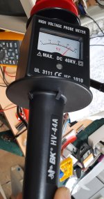
Hooked a signal to it with brightness all the way down and it still looks pretty overvolted. Took a measurement with HV probe, looks like 34Kv. Gotta be honest, I am somewhat skittish with this. The whole time it is sizzling and popping while taking the HV measurement. I sure don't mind to test things, just need some extra reassurance I have the right connection hooked to the tester. I will check the schematic and see if I can find where to connect for the 5.6v feedback.
Generally the EHT should be under 30kV, typically in the 25kV to 27kV vicinity. Likely the EHT over-voltage protection circuit is normal and doing its job. Don't power it again until we figure out the cause of the problem, unless we are forced to.
This is where some magnetic deflection scan theory helps.
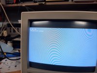
The appearance of the raster, combined with the high EHT, likely tells us why the EHT is too high.
All else equal in magnetic deflection, the size of the scan, is inversely proportional to the square root of the EHT voltage. If there is an isolated fault affecting the EHT alone to increase it significantly, and nothing else, then the scan width will drop and the raster will be under-scanned. We have an image though, which shows the scan width, if anything is a little over-scanned, but still with high EHT.
But the two systems of scanning and EHT generation are linked, so if we see a combination of excessive EHT not associated with decreased scan width, it gives a clue why. (The raster height behaves the same way too, but we cannot put as much stock in that, because the height control may have been adjusted)
What this means is that the fault is due to actual H over-scan: There is a fault, whereby the stored energy in the H yoke coils and LOPT is higher at the end of scan time prior to flyback than normal. This increases both the scan width and the EHT together. This can happen for a number of reasons I will post again later today on what to do next and explain the determinants of the yoke's and output transformer's peak current at the end of scan.
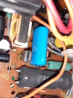
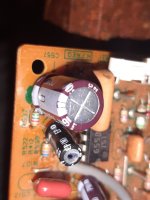
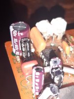
1) Firstly, did you replace the capacitor C1530 and if you did, can you take a photo of the part you put in there ?
2) assuming no issue with that capacitor:
In the H output system, after the H output transistor is switched on, and from the point where the beam is at the center of the CRT face, the current in both the yoke and the flyback transformer's primary, rises at a rate of V/L amps per second, where V is the power supply voltage to the H output stage an L the inductance of each. The peak current is determined by the time that the HOT is switched on for, which is also related to the H scan frequency.
This affects both the scan width and the EHT, because the width relates to the peak yoke current before flyback and the energy stored in the field of the yoke and flyback transformer determines the EHT, because this energy is transferred to the energy of the electric field of the capacitances half way through flyback, where it peaks.
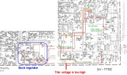
From this and the increased EHT & width together, can deduce that the voltage supplying the Flyback transformer primary circuit and yoke is too high.
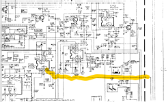
In a multi- standard VDU, to get around the different scan frequencies and different times that the H output transistor is turned on for, they have in this case enclosed the power supply to the Flyback and yoke in a tight feedback loop, as I had highlighted on the previous diagram. Basically the voltage regulator supplying the flyback and H yoke coils is a Buck type, so it can manipulate the power supply voltage below the 125V rail that supplies it.
There is clearly a problem in the feedback loop and the output voltage of the buck regulator will be too high. And the shutdown circuit has detected this.
It is lucky so far that the when the shutdown circuit was disabled that it tolerated the 34kV. At this point, I would recommend release the short on pin 9 to re-enable the shutdown system.
We need to devise a way to power the flyback and yoke from a lower voltage, so that the shutdown does not deploy and the EHT stays normal range or low, so we can fault find the whole feedback loop and the buck-boost regulator controlled by it.
I will work on the method and post later. In the meantime, double check the capacitors and soldering in the buck boost section and the feedback loop.