- VCF South West - June 14 - 16, Davidson-Gundy Alumni Center at University of Texas at Dallas
- VCF West - Aug 2 - 3, Computer History Museum, Mountain View, CA
- VCF Midwest - Sept 7 - 8 2024, Schaumburg, IL
- VCF SoCal - Mid February 2025, Location TBD, Southern CA
- VCF East - April 2025, Infoage Museum, Wall NJ
-
Please review our updated Terms and Rules here
You are using an out of date browser. It may not display this or other websites correctly.
You should upgrade or use an alternative browser.
You should upgrade or use an alternative browser.
Help on monitor issue with Taxan 770 plus, powers on but video collapses.
- Thread starter lowlytech
- Start date
Hugo Holden
Veteran Member
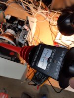
Ok, that looks good.I get 0.30 ohms between those points
Not going to believe this, but I think it is finally working. Was going over the soldering and I happened to move the tweezers on a joint and it broke loose a bit. I reflowed and reassembled and just like that it seems to be working. Cap C423 was the culprit I think. I will let it run for the better part of tomorrow and check the voltages. I really appreciate everyone sticking with me through all the testing and suggestions. Will report back tomorrow after more testing but it looks promising.
Attachments
Hugo Holden
Veteran Member
Not going to believe this, but I think it is finally working. Was going over the soldering and I happened to move the tweezers on a joint and it broke loose a bit. I reflowed and reassembled and just like that it seems to be working. Cap C423 was the culprit I think. I will let it run for the better part of tomorrow and check the voltages. I really appreciate everyone sticking with me through all the testing and suggestions. Will report back tomorrow after more testing but it looks promising.
Though, those components would not really explain why the VDU had the problem it did.I think C423 is in an unrelated part of the V deflection circuitry, and it could not explain why the EHT was 1.4 x too high.
At least there is a lesson here for you to learn.
This is the thing I have been trying to explain to you the whole way along, but you have been slow to pick up on it, and have kept tampering with unrelated parts of the VDU's circuitry.
When there is a fault, what you need to do is to disturb as little as possible. No removing and testing random components in other parts of the circuit.
Each time you manipulate and flex the pcb, if there is a fractured connection, elsewhere, it runs the risk that the VDU could suddenly start working again. This is not as good as it sounds and is not a "repair". It is impossible to find a fractured connection if it had re-connected.
You create an intermittent and latent problem this way. These always come back to haunt you, without exception.
The better situation is that the fault remains, and you can find it by gently probing with the scope. Identify exactly what the fault is, and correct it.
In a thorough World too, if you have really found the exact cause, such as a fractured solder join, then you should be able to re-create the exact same fault, by opening that connection, to convince yourself it was definitely the cause of the fault you were pursuing.
Interestingly, this notion was applied by Koch, in trying to identify the cause of infections, especially see point 3 of Koch's Postulates:
- The microorganism must be found in abundance in all organisms suffering from the disease but should not be found in healthy organisms.
- The microorganism must be isolated from a diseased organism and grown in pure culture.
- The cultured microorganism should cause disease when introduced into a healthy organism.
- The microorganism must be re-isolated from the inoculated, diseased experimental host and identified as being identical to the original specific causative agent.
So alas, I feel the real cause of the fault still resides in your VDU.
When the fault returns, which it most likely will, try not to interfere with pcb & components pulling out parts elsewhere and flexing the pcb.
Instead, set up a test situation with the scope and try to find the cause with as little manipulation to the pcb as possible. I think I know where the cause might be, we will wait and see.
Well shoot, I was hoping that component would have somehow been related to the fault. Before I put it together again for the pretest after fitting the transistor is when I went over all the joints and traces again with a bright bulb and magnifying glass, when I spotted that joint not looking totally right. I only did that cause it is somewhat involved getting the main pcb in and out of the monitor.
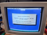
Monitor has been on for about 30 minutes so far this morning. Testing different video modes, etc while the multimeter is on the B test point. So far it seems okay but time will tell. The convergence seems to be off is the most noticeable thing , but the overall brightness seems very good.
I too would like to know 100 percent what caused the issue and if C423 is not it, then we still have an issue. I will unsolder that one leg of C423 just to see what the monitor does after the monitor has had a few hours of power on today. The whole point of the recap was to preserve the CRT for use on my 286 system. So for it to be correct and right is important to me. Unfortunately I don't know much about circuit design and troubleshooting but I do want to learn and get better. Hugo, I have thoroughly enjoyed and am very thankful for your explanations on the circuit functions during our troubleshooting thus far. It is very informative and this type of information is hard to find out there unless you talk to someone that has extensive experience with CRT theory and function. The Zener diode should be delivered today so I will have that when we need it.
Hugo Holden
Veteran Member
At least you know a few things about the fault now:
It was unlikely due to your recap, in that you re-fitted suitable capacitors correctly everywhere.
It is unlikely due to a defective IC, transistor or other faulty component.
Most likely this fault is due to a fractured or faulty solder connection or track on the pcb, and it simply came evident due to the physical manipulation of the pcb during or after the recap process.
The character of the fault suggested that the negative feedback loop, which controls the PWM regulator, was broken prior to the AN6558 OP amp, so the regulator system simply ramped up the output voltage probably to around 1.4 times its normal value increasing the EHT by a similar amount, that initiated shutdown of the HA11235, due to EHT over-voltage being detected.
If the fault returns, try not to physically bump or do anything to the unit, and I will suggest some things to gently test it, to locate the problem.
andy
Experienced Member
I would try gently tapping, and flexing the board to see if you can bring the problem back. If it doesn't, you'll just have to wait and see.
For the convergence error, it's possible you bumped the convergence rings on the CRT neck while working on it. It doesn't take much. I've also found that the convergence is slightly affected by the high voltage setting. Since you moved the HV adjustment during testing, it's probably not set precisely the same as before.
For the convergence error, it's possible you bumped the convergence rings on the CRT neck while working on it. It doesn't take much. I've also found that the convergence is slightly affected by the high voltage setting. Since you moved the HV adjustment during testing, it's probably not set precisely the same as before.
Hugo Holden
Veteran Member
Of course it is possible that when the re-cap was done, that the faulty connection happened in the locality, nearby where you changed a cap, where the connection was poor or weak in the first place.
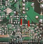
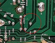
As one example, look at the attached photo. Of course it is very difficult to assess this on a photo, without having the pcb on the desk with bright light and magnification.
Where a cap was replaced you can see a scuff mark on the pcb coating where a tool scraped across the surface, in the region of a suspicious solder join. This is one of the very important connections that brings the feedback signal from pin 10 of the flyback, to the OP amp circuit. If this goes open circuit, it generates your exact fault. The photo at least is suggestive of a thin dark 360 degree ring fracture in the soldering, that is not visible on other similar sized joins nearby. But the photo resolution is limited.
This was why I asked you to do the test with the meter, because that test should have shown the DC resistance of the flyback between pins 10 & 12 taking this whole trackwork and soldering into account. Which it did, but possibly, by then, this join if it was defective, had re-connected.
So if the unit fails again, re-do the test with the meter, which you could do from the top of the board and see if it has gone high resistance. And you could also try to move the wire tail in the hole and see if it appears that join is fractured.
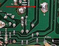
This is by no means the only possible cause. One thing that can happen is, when items, like the flyback transformer, or other parts are in storage before use, they can get oxides on their pin surfaces which degrade the quality of the solder join, Bigger heavier objects are more likely to have the solder joins fail because the forces are higher and due to thermal cycling. It could also be a defective solder join to pins 10 & 12. In addition, the copper track work can fracture, and sometimes the fracture line is very thin and hard to spot, there are a couple of suspicious areas for that too. In the past for example, if the VDU has been dropped, these tend to occur near the heavier objects on the pcb. For example, it is possible that the thin line seen on the track work represents a track fracture, but with a photo, it is not possible to be sure. Another reason why electrical testing is a better option.
As one example, look at the attached photo. Of course it is very difficult to assess this on a photo, without having the pcb on the desk with bright light and magnification.
Where a cap was replaced you can see a scuff mark on the pcb coating where a tool scraped across the surface, in the region of a suspicious solder join. This is one of the very important connections that brings the feedback signal from pin 10 of the flyback, to the OP amp circuit. If this goes open circuit, it generates your exact fault. The photo at least is suggestive of a thin dark 360 degree ring fracture in the soldering, that is not visible on other similar sized joins nearby. But the photo resolution is limited.
This was why I asked you to do the test with the meter, because that test should have shown the DC resistance of the flyback between pins 10 & 12 taking this whole trackwork and soldering into account. Which it did, but possibly, by then, this join if it was defective, had re-connected.
So if the unit fails again, re-do the test with the meter, which you could do from the top of the board and see if it has gone high resistance. And you could also try to move the wire tail in the hole and see if it appears that join is fractured.
This is by no means the only possible cause. One thing that can happen is, when items, like the flyback transformer, or other parts are in storage before use, they can get oxides on their pin surfaces which degrade the quality of the solder join, Bigger heavier objects are more likely to have the solder joins fail because the forces are higher and due to thermal cycling. It could also be a defective solder join to pins 10 & 12. In addition, the copper track work can fracture, and sometimes the fracture line is very thin and hard to spot, there are a couple of suspicious areas for that too. In the past for example, if the VDU has been dropped, these tend to occur near the heavier objects on the pcb. For example, it is possible that the thin line seen on the track work represents a track fracture, but with a photo, it is not possible to be sure. Another reason why electrical testing is a better option.
Attachments
Last edited:
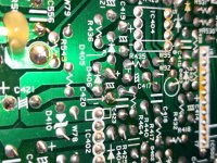
Yeah I see what your talking about with the way that connection looks questionable where it is circled in red. I know I haven't dropped this, but the monitor was a purchase from ebay, so the shipping or previous owner could have definitely been a factor in rough handling. I figured I broke it since it worked when I first got it, but again I only had it on for a few days before I decided to do the recap.
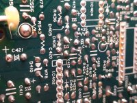
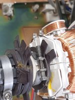
The monitor had convergence issues before the recap. It isn't bad, but toward the top and corners is where I notice it. Also it seems to be worse in 640x350 resolutions. The rings Andy is talking about are these in this pic? I have always been pretty reserved about keeping about a foot away from the tube anytime it is on. Do you just adjust these by hand while it is on, or do you use plastic sticks? The back set of rings still seem to be held in place pretty well to the tube, but the front two do turn freely on the tube as it seems the glue bond has broke, but the 2 rings are still bonded together so they turn together.
The monitor has been on for about 4 hours today. I gently tried to tap the pcb and move it a bit on the bench and never had the monitor show any issues. I now have it torn down again and can confirm the joint does look bad to me, but I did not see any crack on the trace itself.
Attachments
andy
Experienced Member
You adjust them by hand. They are plastic, and there are no high voltages there. Just avoid touching any exposed connections on the yoke, or CRT socket board. The rings only adjust the center convergence.
Hugo Holden
Veteran Member
I wouldn't adjust the rings initially, it could just be that the CRT requires de-Gaussing. They normally have an internal de-Gaussing coil, but if the shadow mask has acquired some magnetism from an external field, the internal coil cannot sometimes have enough effect to fully de-Gauss it. I would use a de-Gaussing wand on it first. Prior to deciding if any other adjustments were required. The wand is used from the front face of the CRT, the wand is never put near the rear of it, never near the yoke or gun assembly or pcb as it induces voltages in coils & conductors. Generally it would be done while it was in its cabinet from the crt front. There is a technique to it, to get the amplitude of the alternating magnetic field to fade out, leaving no residual field in the shadow mask, read up on how to do it. The wands are quite cheap on ebay now.
Hugo Holden
Veteran Member
If you manipulate the wire tail from the link wire passing through that joint, is it actually fractured, or not ? (I hope you haven't re-soldered it yet)I now have it torn down again and can confirm the joint does look bad to me, but I did not see any crack on the trace itself.
One thing you could do, is de-solder pins 10 and 12 of the flyback with solder wick and inspect the solder on the pin's surfaces, if it is bad, scrape the pins and re-solder them. Then with an insulated link wire added to the bottom of the pcb, run it from pin 10, all the way down to where the track terminates near the AN6558 circuitry, to bypass that entire track length. If the VDU ever fails again in the same manner, with that bypass wire present, then all of that trackwork, links and the soldering to pin 10 and 12 of the flyback will be excluded from the investigations.
I looked at the joint in question and took the tweezers to it and it didn't really break loose. I just now got it together and powered back on and it still is working at the moment. The convergence issue isn't that bad and I will check into a degausser coil. The main thing is magenta colored boxes have a bit of red on the left and blue on the right. Otherwise it looks good. I know if I try and get that extra 5 percent I will end up making it worse and dropping 15 percent. Too many adjustments on those convergence rings. I will post back if the monitor drops out again. Gonna try to give it a few hours every day this coming week to test it out.
Good idea to bypass with a wire. Will look into that if the monitor comes up with the same issue.
Good idea to bypass with a wire. Will look into that if the monitor comes up with the same issue.
andy
Experienced Member
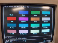
Degaussing won't help the convergence, it just removes color purity problems. Mark the location of the rings by drawing a white line across them before you move them. Two of the rings are for purity/ beam landing (make the beams only hit the correct color dots), two converge then red with the blue, and two converge the red and blue with the green. It won't take a large adjustment.
Hugo Holden
Veteran Member
That is true, however a novice with color VDU's often mistakes the two problems, so its worth degaussing it first, before touching the rings.Degaussing won't help the convergence, it just removes color purity problems. Mark the location of the rings by drawing a white line across them before you move them. Two of the rings are for purity/ beam landing (make the beams only hit the correct color dots), two converge then red with the blue, and two converge the red and blue with the green. It won't take a large adjustment.
One thing to understand about the convergence, it is often never perfect and it is a matter of averaging the errors, and especially towards the corners, often some errors still remain with the best compromise.
andy
Experienced Member
That is true, however a novice with color VDU's often mistakes the two problems, so its worth degaussing it first, before touching the rings.
One thing to understand about the convergence, it is often never perfect and it is a matter of averaging the errors, and especially towards the corners, often some errors still remain with the best compromise.
I agree that it's a good practice to degauss before adjusting anything on a CRT.
When going by the book, you're supposed to adjust the convergence rings for perfect center convergence, but I too have have found that a compromise is usually necessary. Often, an almost imperceptible compromise in center convergence will make a noticeable improvement at the edges.
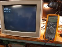
I think I am gonna leave the rings where they are. I can't complain at all at the current state, and finding a multisync TTL monitor these days is hard to do let alone one that doesn't have a tired tube. The only thing that seems to be off is the magenta color makes my eyes cross when I look at it. It is funny, but the photos of the magenta don't really show the intensity of the color bleed, but you can kind of see it. The other colors look great. However in an app or game with everyday usage, I think it would be hard to see this magenta anomaly.
Attachments

Hugo Holden
Veteran Member
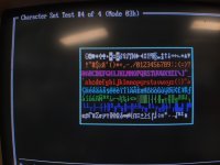
The white thin line border is a better test for the convergence, which looks fine. The errors around the magenta on the horizontal meridian only, are likely due to timing errors in the R & B signals generating the magenta and nothing to do with the convergence itself. Good thing you didn't adjust the magnets.I think I am gonna leave the rings where they are. I can't complain at all at the current state, and finding a multisync TTL monitor these days is hard to do let alone one that doesn't have a tired tube. The only thing that seems to be off is the magenta color makes my eyes cross when I look at it. It is funny, but the photos of the magenta don't really show the intensity of the color bleed, but you can kind of see it. The other colors look great. However in an app or game with everyday usage, I think it would be hard to see this magenta anomaly.
If you look at the cyan, it has a slightly green leading edge, meaning the blue signal has a phase delay. You cannot see that on blue alone, but on magenta that causes the red to show on the leading edge. Yellow is fine, meaning there are no timing errors on the red & green.
A reduction in high frequency response in the blue channel can cause this phase delay, but before you could conclude that was in the VDU, you would have to try your source signal on another VDU, known to be good, because this issue could be in the source signal and not in the Taxan VDU.
Last edited:
andy
Experienced Member
Red-blue convergence errors are most obvious when viewing magenta. In fact, when adjusting the red-blue convergence, I do it with a magenta pattern on the screen. The green tends to visually tie the red and blue together, even if they're pretty far off. If you look at the white border, you'll see that the left side of the line has a red shadow, and the right side has a blue shadow. It won't hurt anything (other than your eyes) to leave it as is, but I couldn't live with that much convergence error.