Upcoming Events:
- VCF South West - June 14 - 16, Davidson-Gundy Alumni Center at University of Texas at Dallas
- VCF West - Aug 2 - 3, Computer History Museum, Mountain View, CA
- VCF Midwest - Sept 7 - 8 2024, Schaumburg, IL
- VCF SoCal - Mid February 2025, Location TBD, Southern CA
- VCF East - April 2025, Infoage Museum, Wall NJ
-
Please review our updated Terms and Rules here
You are using an out of date browser. It may not display this or other websites correctly.
You should upgrade or use an alternative browser.
You should upgrade or use an alternative browser.
Cromemco dazzler replica project
- Thread starter Hugo Holden
- Start date
daver2
10k Member
Always good to ask though...
No such thing as a stupid question - before we bend out the wrong pin!
Dave
No such thing as a stupid question - before we bend out the wrong pin!
Dave
daver2
10k Member
Just out of interest I looked up the IEEE 696 (1983) specification.
The address bus should be valid for the entire read (pDBIN) cycle with minimum specifications for the setup and hold time prior/post pDBIN edges.
As such, there should be no requirement for any latches on the address bus at all.
That doesn't mean that S-100 equipment is compliant with this specification of course.
Dave
daver2
10k Member
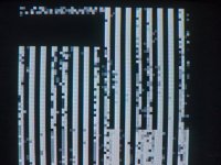
Oh, that looks much better now - it is (sort of) random...
I assume you put the 2 ICs back in...
Can you repeat our previous tests (that didn't work) where we were checking the state of the eight (8) data input bits after IC49/1 has gone high.
We always got a HIGH signal.
Hopefully (now) we will see both HIGH and LOW signals - and it changing - during the time IC49/1 is HIGH.
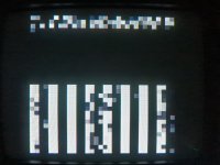
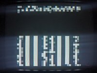
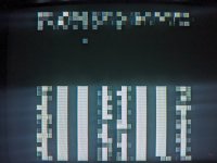
With D5=0 I see the data pattern (in the RAM) is also present in the top left quadrant when D5=1 (which it should be).
The large black band may be where RDOS has initialised the memory?
Dave
daver2
10k Member
He he...
Fair enough !
!
OK, I can walk you through checking the colour out - but let's leave that till tomorrow now.
Let us bask in our success for a day!
Dave
Fair enough
OK, I can walk you through checking the colour out - but let's leave that till tomorrow now.
Let us bask in our success for a day!
Dave
daver2
10k Member
No problem.
I have learnt a lot in the process myself - so we have a win win situation.
Dave
I have learnt a lot in the process myself - so we have a win win situation.
Dave
daver2
10k Member
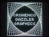
More impressive with colour though (even if it is missing the 'u')!
Since we have sorted the DMA out now, it is looking like the pixel control is looking OK.
When the dazzler demo gets to a definite colour screen, can you post an oscilloscope trace of a line of video. You did this a while back.
It will be interesting to see whether there is the colour burst and chroma information present.
Dave
Hahaha come on, the Cromemco guys were American, just keep your funky spelling.More impressive with colour though (even if it is missing the 'u')!
When the dazzler demo gets to a definite colour screen, can you post an oscilloscope trace of a line of video. You did this a while back.
Would it be better to use KSCOPE? That would certainly be in color. It works too, BTW but is also not in color.
daver2
10k Member
By all means use KSCOPE.
Dave
Dave
daver2
10k Member
When you have done that, it might also be worth running up my test program and setting D4=1 to see what happens.
If the colour is switched 'on', even if the red and green colour potentiometers are misadjusted, blue should still be working.
Dave
If the colour is switched 'on', even if the red and green colour potentiometers are misadjusted, blue should still be working.
Dave
This is while KSCOPE was running.. I still have no idea how to really interpret this, let me know if anything's missing or if this shows you what you're looking for?
I'll have time for more tests later this evening and can try the D4 test
I'll have time for more tests later this evening and can try the D4 test
daver2
10k Member
The colour burst is definitely present.
However, I get the impression from the DACs that the colour burst is always present - even in monochrome...
It is pretty difficult to see the chroma information. I always prefer a solid color screen - which we can now do by using RDOS commands...
But that is for tomorrow.
Dave
However, I get the impression from the DACs that the colour burst is always present - even in monochrome...
It is pretty difficult to see the chroma information. I always prefer a solid color screen - which we can now do by using RDOS commands...
But that is for tomorrow.
Dave
Hugo Holden
Veteran Member
I think from previous tests, that when we checked this issue, the R, G & B color color carriers were being gated out of IC 17 pins 12.6 & 8. Extra carrier level comes out of IC16 pins 12,6 & 8 when thee intensity line is high, to boost the level. But we saw no color carriers on the output video signal, only the burst was there.
All of the signals (Color carriers, Color Burst, RG&B luminance & intensity) are resistively mixed at the input to the three transistor output amplifier. This input, behaves exactly like negative input of an OP amp, when there is negative feedback around the OP amp, in that it acts as a Virtual Earth, so that the mixing signals do not interfere with each other, this is because of the negative feedback around the amplifier.
This means though, in terms of voltage levels at the input (at the base of the input 2N3904 on the left) very little if any dynamic voltages will be seen with the scope, because the current from the negative feedback via the 1.5k resistor cancels them to zero.
Since the burst was there at the video output, and we saw color carriers on the output of IC 17 (that needs re-checking) I was wondering if somehow the resistors for the color mix had not made the link from the IC 17 & 16's outputs to the virtual earth input point at the amplifier input, but I think @nullvalue had already checked the connections.,
Other things that can make the signal go into monochrome, when the burst( and color carriers are off frequency) or the burst too low, the particular VDU can deploy its color killer and go into monochrome mode this way, but I don't think that is too likely because we could not see any color carriers on the video signal on previous scope tests which was suspicious for a problem and the frequency had been checked and the burst level looked reasonable.
Last edited:
Gary C
Veteran Member
Fantastic
Can I ask that you check my post #817 as I want to make sure I am on top of the errors in the PCB we have found so far (which appear to be minimal and a do have a couple of PCB sets left if anyone wants them, note they are HASL rather than ENIG though and dont have hard gold fingers)
But this is exciting and makes those hours of tracing out the tracks in Kicad worthwhile
Last edited:
daver2
10k Member
Gary,
I haven't been keeping track of the actual modifications. It will be much easier for @nullvalue to look at his board...
That was an evil thing for the RAM board to be messing us up... I had a hunch - but that is not the same thing as having evidence...
Dave
I haven't been keeping track of the actual modifications. It will be much easier for @nullvalue to look at his board...
That was an evil thing for the RAM board to be messing us up... I had a hunch - but that is not the same thing as having evidence...
Dave

