• Please review our updated Terms and Rules here

3032 - 2001N Repair

>>> Not following, which top?

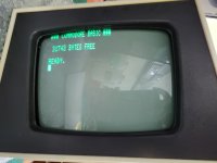
There is the "*** COMMODORE BASIC ***" message missing from the top line of the monitor...
Ah, yes. But that is because the Vertical size is so big that that line is painted off the top of the display area.
.
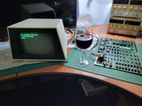
Just found the %$^&* culprit, pictures incoming. First going to pour a glass of red. In the mean time, I'll take bets on what it was. :)
 
>>> Just found the %$^&* culprit, pictures incoming. First going to pour a glass of red. In the mean time, I'll take bets on what it was

A solder splash (or some other contaminant)...

What's first prize :)?

Dave
 
I was going to suggest double checking the diodes CR8 and CR12 for leakage. When the TTL input signal goes high, the diodes un-conduct and allow the 1uF capacitor & height pot to produce that sawtooth shape during scan time.

On the topic of the feedback as well as the + feedback for linearity, and the neg DC feedback for the working point, there is AC negative feedback via the 0.15uF capacitor, this sets the bandwidth of the amplifier and limits its upper high frequency response, if that went awry or had a bad connection, then the amplifier gain would drastically increase for transients.
 
Last edited:
With the reference measurements from a working monitor, it really felt like there is something wrong, right on the input of the V-Drive circuit. It's like the 5V TTL input is directly driving Q6 making one think there is a shorted component. But I've already removed and tested the components driving Q6. So I thought it might be a short, or open circuit, on the PCB itself. Had a good look under magnification, but did not see anything. Also, did not measure anything that looks like a short across the components connecting V-Drive to Q6. Decided to reflow every connection on the board. Which was probably a good idea as there were a few distinct 'pops' which indicates some joints were under stress and this only can lead to a dry joint at some point.
.
Unfortunately, this made no difference.
.
By now I was convinced it must be something on the input circuit. The passive components really looked OK so I relooked at the two small signal diodes, CR8 and CR12. Taking them out, they pass my multimeter test and even show the correct forward voltage o the component tester. Decided to replace them in any case.
.
V-Drive Circuit-Diodes.jpg
.
And, lo and behold, it fixed the flippen problem!!
.
20230709_190244.jpg
.
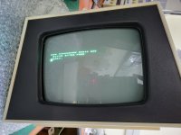
The Vertical Size preset now works properly, going from "Too big":
20230709_185552.jpg
.
To "Too small":
20230709_185537.jpg
.
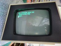
To "Just Right":
20230709_185608.jpg
.
I've got the two offending diodes and will post some pics of what my component tester says about them compared to new signal diodes. Hopefully the people who actually understand what happens at the silicone junction can explain how a seemingly working diode can misbehave like this.
 
I was going to suggest double checking the diodes CR8 and CR12 for leakage. When the TTL input signal goes high, the diodes un-conduct and allow the 1uF capacitor & height pot to produce that sawtooth shape during scan time.
.
You win the bottle of SA red! :)
.
Been wanting to come visit your part of the world for a long time. Next time I'm there, I'll personally deliver it to you. :)
 
>>> Just found the %$^&* culprit, pictures incoming. First going to pour a glass of red. In the mean time, I'll take bets on what it was

A solder splash (or some other contaminant)...

What's first prize :)?

Dave
Bottle of SA's finest. Which I'll happily consume with you! :) :)
 
The input area is a very high resistance circuit, 500k assuming the pot in the middle (this is why I moved to a 1uF MKT capacitor in my VDU) so it would only take a leakage resistance in the diode/s of a meg ohm or so to cause trouble and maybe the diode tester would not detect that. It might show up on an analog meter with a x 10k resistance range, or a VTVM on resistance range, or perhaps just a DVM checking the diodes fwd and reverse.

It would be worth subjecting the diodes to magnification, do they have the correct markings (or any) are they the correct parts. They are in a fairly low stress application, so it is hard to imagine what caused them to fail. The 1N4148, assuming a genuine part, have quite impressive reverse voltage and pulse current ratings for their physical size, and there is little here to stress them, though if the B-E junction of Q6 had failed in the past and gone O/C, it is possible that a high voltage transient from the Yoke, coupled via the feedback pathway, could possibly have damaged them, but even that seems unlikely.
 
Last edited:
Good job there. You now have a Goldilock's monitor - not too big, not too small but just right!

Incidentally, diodes are made of silicon not silicone...

Yes, I would be interested in what the problem was. I wonder if they are exhibiting a characteristic like a zener diode?

Dave
 
It is unlikely that both CR8 and CR12 faulty.

It is also unlikely that they have gone open circuit.

If CR8 has gone short circuit (or leaky) that would pull down the lower end of R12 when it shouldn't (i.e. when the VDRIVE signal is HIGH).

If CR12 has gone short circuit (or leaky) that would cause C9 to charge up quicker via the sneak path.

Dave
 
Will try and see if I can test them as leaky.

This makes me wonder if I should not just replace the other 2 diodes in the V-Drive circuit. And potentially any others, in the rest of the circuit.

I'm not normally for replacing components, "just because" (this trend in the vintage computing world to "re-cap" everything, a good example and drives me insame watching how people buther perfectly working computers), but monitors are definitely a much harsher environment for electronics.

What's the common wisdom here? While the monitor is open, should anything be replaced in a preventative way?
 
What's the common wisdom here? While the monitor is open, should anything be replaced in a preventative way?
Not really. I cannot think of anything (perhaps aside from the electrolytics) that could be replaced in a preventative way (perhaps just one thing). Even then, it appears that most of these VDU's were originally fitted with good quality Nichicon electrolytic caps and they are generally ok.

But there is the one exception, the electrolytic cap that filters the negative supply rail to the brightness control, needs to be about 10 times bigger in uF value. Oddly, it would have been about perfect, as they had it, if the brightness control pot was a 1M Ohm value (not 100k) also 1M Ohm for that part is a more typical value because a CRT's grid current is negligible. With the 100k pot they have there it is better to increase the capacitor from around 3.3uF to 330uF (or at least 220uF), otherwise, when the VDU is turned off, the high intensity beam can burn the CRT phosphor near the screen center (the old after glow spot problem of TV style CRT's).

Perhaps one other thing, in these VDU's they pushed the 12V regulator pretty hard with thermal dissipation. It manages just because of the very large heatsink it has. It is worth making sure that it is well thermally bonded to the heat sink with fresh thermal compond. If it has a screw and nut do that and securely tighten the nut. If it has a rivet, which some units had, it can be a problem as it distorts the tab on the TO-220 device and it weakens the thermal coupling to the heat sink especially if there is a paucity of thermal compound and it has dried and gone powdery.

Also the two TO-220 package vertical scan output transistors were "borderline" for requiring a heat flag on them. Some 9" VDU's have them some not. It is worth fitting those I think, I did for my 9" VDU's.

Then there are the other 4 things you could do, that are pretty optional, described in my article:

1) add the Germanium energy recovery rectifier to improve the left sided H scan linearity.
2) change the yoke coupling capacitor from 10uF to 8 or 8.2uF to improve the H scan linearity too.
3) add the zener diode to help protect the unit's horizontal output stage if the H.Drive signal from the computer goes awry.
and if you get really fanatical like me:
4) add a focus potentiometer, to gain the best compromise between corner and center focus on the CRT.
 
Last edited:
Thanks Hugo,
.
Interestingly, in both my 9" CRTs, I don't get the "white spot" problem. I do intend to increase the cap you identified in any case as it can have only a positive benefit.
 
Thanks Hugo,
.
Interestingly, in both my 9" CRTs, I don't get the "white spot" problem. I do intend to increase the cap you identified in any case as it can have only a positive benefit.
It is actually pretty easy to miss it, in many cases it only appears about 15 or so seconds after the VDU is turned off, and at that point most people are not looking at the screen and looking elsewhere. It will probably be there, but it may be less intense than usual, it partly depends on the CRT's cathode emission. Turn out the light and turn the unit off and watch & wait and see if you can see it. If it is low intensity there is little point in changing the cap value.
 
Back
Top