• Please review our updated Terms and Rules here

5160 - unknown component?

lordhailsham

Member
Joined
Apr 18, 2018
Messages
30
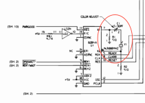
Hey folks, I am merrily fixing up my 5160 (following the very wonderful guide on minuszerodegrees.net) and feel that this broken (ceramic capacitor? labelled C1) needs to be fixed before I go much further.

If anyone can give me any tips about this I'd be most grateful,
thanks!
Andy
Capture.PNG
 
That is the trimming capacitor for colorburst. It's used specifically on cards like the original IBM Color Graphics Adapter when you were using the composite output but is otherwise unused.
 
Welcome to these forums.

... on minuszerodegrees.net
So you will have seen the 'Capacitor C1' section of [here].

Yes, it is ceramic.

( If desired, vintage replacements exist. For example, having a look on eBay, I see item 185298911880, although maybe that one's pin spacing needs to be investigated. )
 
Last edited:
thank you both for the info! :cool:

So given the cautions about soldering directly onto the motherboard, would it be something I could safely <COUGH> ignore or remove for now? Presumably if I have a CGA card I won't be at the mercy of this adjustment capacitor?

cheers.... Andy
 
The capacitor matters if you have an older CGA card and you feed your monitor from the composite video output of the card. If you're using the RGBI output, it has no effect.
Hi Chuck - I don't actually possess a CGA monitor - I was thinking of getting a CGA-to-HDMI adapter kit on the ebays... but now I see there's a composite video, that might be the way to go. Not sure if I have a newer or older video card, elt me check
cheers! :biggrin:
 
So given the cautions about soldering directly onto the motherboard, would it be something I could safely <COUGH> ignore ...
You can ignore the damage if the capacitor is electrically sound.

... or remove for now?
Note that the capacitor is a necessary component in the circuity that generates various clocks. See the adjustable capacitor at the far left of the diagram at [here]. Without the capacitor, there will be no clocks.

As a long term solution, if you are not in the situation that Chuck indicated in post #6, then you can use a fixed value capacitor (rather than an adjustable one).
Or you can use a fixed value capacitor as a short term fix whilst waiting for an adjustable one to arrive.
 
I pulled out an IBM 5150 motherboard and an IBM 5160 one. I see that for the adjustable (variable) capacitor, the inter-hole spacing is slightly different between the two motherboards. Important information for those who are seeking an exact fit.
That capacitor i used and refer to in the thread is NOT AND EXACT fit.. But it installed fine and works fine. Thats all I cared about.
 
I have to admit that I've been puzzled by the trimmer ever since I bought my 5150 back in the dark ages. Exactly what did the geniuses at Boca Raton expect the average user to do with the cap? It's deep inside the machine and not addressed at all in the Guide To Operations and its purpose is rather narrow. All I can guess is that there was some stage in the QA testing where there was a worker with a frequency meter and an alignment tool tweaking things.
 
Exactly what did the geniuses at Boca Raton expect the average user to do with the cap? It's deep inside the machine and not addressed at all in the Guide To Operations and its purpose is rather narrow. All I can guess is that there was some stage in the QA testing where there was a worker with a frequency meter and an alignment tool tweaking things.
Probably nothing I would imagine. It is part of the oscillator circuit that eventually provides the CPU clock among other things (more critically things to do with video). Its not really something the user should go messing with, unless they know what they are doing and have the tools to dial it in correctly.

So yes I'd imagine that in the factory someone sat there with a frequency counter or similar, the correct kind of screwdriver (it matters!), and their tongue at the right angle. :)

Image from sheet 1 of the schematic in the 5160 Technical Reference.
 

Attachments

  • Screenshot 2023-01-15 at 15.16.21.png
    Screenshot 2023-01-15 at 15.16.21.png
    55.2 KB · Views: 6
So why didn't the geniuses at Boca simply place a tweakable oscillator on the CGA card? It's not as if they were trying to save money; witness the dead ends on the MDA card.

Has anyone run into a situation where dinking with the trimmer has been necessary?
 
Sounds like a good question to ask someone that was involved in the design.

My best guess is they might have figured there was some advantage to keeping everything synchronised to one clock or a derivative of.

Or maybe they figured they'd just put a higher quality crystal on the motherboard and distribute its signal all over the board so that everything could benefit.

🤷
 
So why didn't the geniuses at Boca simply place a tweakable oscillator on the CGA card? It's not as if they were trying to save money; witness the dead ends on the MDA card.

Has anyone run into a situation where dinking with the trimmer has been necessary?
My only guess would be "to save $0.5", or whatever was the cost of the oscillator circuit. It is likely that 14.31818 MHz crystals were cheap, being a popular frequency used for NTSC colorburst.
Ideally, they would use 5 MHz clock for the CPU instead of 4.77 MHz (5% performance improvement!). And whatever clock frequency is needed for the CGA card would be generated on that card.

To answer the OP question, it is likely that the motherboard will work just fine with the broken trim cap. The CPU/OSC frequency might be just a tiny bit off, unnoticeable unless the computer is used with a CGA card and a color composite display.
 
To answer the OP question, it is likely that the motherboard will work just fine with the broken trim cap.
I guess it depends on how it is broken. Not adjustable is probably fine. But the cap is in series with the crystal so if it is non conductive the oscillator may not work at all.
 
Back
Top