• Please review our updated Terms and Rules here

8032-SK Restoration

and the char rom is in a socket, did you have an idea ?
What I was thinking was removing the character generator and linking the data outputs from the character generator (that feed the parallel to serial shift register) to defined states of 0V and +5V (via a resistor of course). This should result in a stable vertical line pattern (replicated for each character position) on the screen.

It would give you confidence that everything after the character generator is OK.

Dave
 
I just noticed that the characters in your video are mirrored.. is this your camera or does it really look like that?
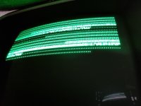
 
I just noticed that the characters in your video are mirrored.. is this your camera or does it really look like that?
As its an SK, the case opens from the back, so the monitor is facing away from me and balanced against a boom handle and the wall, so it was videoed with the front facing camera, which of course makes a mirror image.
 
Ah yes, in that case it makes sense to look at the screen that way... you could try checking OSD then if you have the same issue per chance... but I don't want to disturb Dave's fault finding process here, it just looked like almost the same problem.
 
Sram at uc7 was showing very long wave on d0 to d3 I think it was exactly what you were describing powerlot, the outputs were so slow, they just merged into one, swapped and a bit of progress

20220705_135513.jpg

Now with flipped image !

So, PETTEST is working but is finding some main memory errors, but also seems some SRAM problem, but its odd that its a block rather than odd/even ?

Ahhh, just re-read the PETTEST instructions, so the VDU test must have passes this time and onto the memory test ?
 
Last edited:
So the first 256 bytes are failing both $55 & $AA. How do I interpret the characters it produces ?
 
Nice, what are the ODDs... was it a MOS chip? Mine was an MPS 2114 dated 3780.

Fortunately all my DRAM ICs were good, so can't help you there...
 
I think it is failing because main RAM (low 16K) has bit 7 permanently at a '1'.

I think it has stopped at the 'fill the RAM with $00, $01, ... $FF and verify that we can read the same back' test.

If it doesn't read the correct pattern back, it displays the character that it found.

In this case, all of the characters in error that are displayed are inverse video - signifying that bit 7 is set when it shouldn't be.

It could either be a DRAM chip, or it could be one bit of a data buffer. I would go on probabilities though and go for the DRAM chip.

Excitement over, back to reviewing documents...

Dave
 
Cheers Dave.

Will have a look next time I get a chance. Have to do some painting now, then its back to work :(
 
Ah, so the characters after the b & g are ASCII (oops, PETSCII) of the number read back from the DRAM. Strange that they increment by 1 ? (though just had a deja vu moment, is this pattern expected due to the way the test works ?)

Also, as its writing the same pattern of alternate 1's and 0's to each bit, I surmised that the DO/DI on each chip should show a similar pattern, but I noted that A5 (bit 7) doesn't. I have taken A5 (and A4) out and they test good. This does point in favour of your theory Dave but its either not the RAM or my chip tester isn't.
 
Last edited:
Ah, so the characters after the b & g are ASCII of the number read back from the DRAM. Strange that they increment by 1 ?

Not if I store $00 into address $0000 and then read back $80. I will then get an inverse '@' symbol as the error report.

If I then store $01 into address $0001 and then read back $81. I will then get an inverse 'A' symbols as the error report.

And so forth...

You have to understand that the low byte of the address of the RAM is stored into the RAM and that is what is expected to be read back.

The 'smart' people should observe that that is the initial display that the VDU RAM test shows. You then look at the sequence of 'g' and 'b' characters to see if there is a nice, logical pattern of stuck address or data lines - and then confirm it with the error characters that are displayed.

I suspect if you count the 'b' and 'g' characters you observe I will guess that you get a continuous sequence of 128 'b' characters followed by a continuous sequence of 'g' characters. This would indicate either address line 7 is faulty or data line 7 is faulty.

This then repeats for page 1 in the same way as page 0.

In Version 5 I am trying to improve the page 0 and 1 RAM test to try and clear up some of these oddities. Unfortunately, I have to do everything using registers (I can't use the page 0 RAM because I don't know if it works yet!). This limits the complexity of the testing. However, using too simple a test lets a few errors slip through the net only to cause problems with later tests.

Dave
 
Ah, I thought it wrote $55 then $AA in turn in this test ?

Doh !

RTFM !

Yes, incrementing. That helps.
 
I was going to say that - but I resisted the temptation.

It also does an AA 55 test (and 00 FF test) as well. I thought that would route out quite a few problems - but a couple evade detection still!

I have another (more thorough) test I 'borrowed'...

Dave
 
Its a fantastic tool that has fixed at least two machines I've been working on. (or one twice, can't quite remember)

I really expected the DRAM to be faulty, but it tests fine.
 
Last edited:
So, looking at it logically, addresses up to and including 0111 1111 fail but 1000 0000 to 1111 1111 work.

That would suggest that something is wrong with bit 7 of the address, but surely if it was stuck it would read and write to the same location and be unable to tell the difference ?

Thinking out loud, I wonder if refresh isnt working on that row but they would default to 0 ?

Humm
 
So
RAS with a bit pattern of 000000 to 111111 then a CAS of 000000 and bit 7 returns as 1 when it should be 0 and all other bits ok
then RAS with a bit pattern of 000000 to 111111 then a CAS of 000001 and bit 7 returns as 0.
from the same chip ?
Or am I being stupid

So why would CAS being 000000 make it not work ? If it was something else on the databus surely every one of the memory locations in the first page would be defective.

More poking about required as its theory ATM as once again I am remote from the machine.
 
I think it is failing because main RAM (low 16K) has bit 7 permanently at a '1'.

I think it has stopped at the 'fill the RAM with $00, $01, ... $FF and verify that we can read the same back' test.

If it doesn't read the correct pattern back, it displays the character that it found.

In this case, all of the characters in error that are displayed are inverse video - signifying that bit 7 is set when it shouldn't be.

It could either be a DRAM chip, or it could be one bit of a data buffer. I would go on probabilities though and go for the DRAM chip.

Excitement over, back to reviewing documents...

Dave

Still a bit stuck (humm, no pun intended !)

Inverse (reverse) is stored as bit 7 ? Just to be clear that is D7 dataline ? and therefore IC UA5 ?

checked UE8, UE9 & UE10, UA4 & UA5 all ok and not sure where to head next. Trouble is, most other things are common to the first and second 128 bytes of memory

any ideas people ?

What I also dont get, it writes $00 to say address $0000 and gets back an @ in inverse, what bit pattern is that. @ is $40 or 0100 0000 but in inverse ?

If it was some other chip on the data bus such as the VIA, that should affect every memory location
 
Last edited:
Back
Top