• Please review our updated Terms and Rules here

8085 'S100' Pinsetter?

falter

Veteran Member
Joined
Jan 22, 2011
Messages
6,580
Location
Vancouver, BC
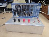
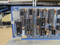
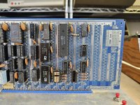
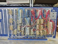
Picked this up a while ago... definitely am addicted to homebrew looking stuff. I think I counted 100 pins, so I think this is an S100 'protoboard'? Anyway, it appears to be a fairly self contained 8085 SBC. The ROMs are interesting. In one of the ROMs there is some text to the effect of 'WVU Supermonitor', which has me thinking, West Virginia University? There is also a mention of a mention of a Dr. Shortwout "Instructor". Looks like an electrical engineering final project. The programmer apparently was Daniel R. Van Clief, and it seems to be programmed to run a pinsetter for a bowling alley. Kinda neat! I kind of wondered about the design because it feels like something from the 70s rather than early 80s.

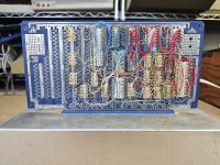
Not sure what the power inputs are but one seems to be +5V, the other I'm guessing might be a negative voltage for serial comms? Curious what the 'Supermonitor' can do - if it was something all purpose WVU had that got adapted by students for different projects.

Link to ROMs here.
 

Attachments

  • 20230912_203020.jpg
    20230912_203020.jpg
    3.7 MB · Views: 37
  • 20230912_203025.jpg
    20230912_203025.jpg
    4.4 MB · Views: 37
  • 20230912_203029.jpg
    20230912_203029.jpg
    4.3 MB · Views: 33
  • 20230912_203031.jpg
    20230912_203031.jpg
    4.5 MB · Views: 34
  • 20230912_203041.jpg
    20230912_203041.jpg
    4.6 MB · Views: 32
  • 20230912_203043.jpg
    20230912_203043.jpg
    5.1 MB · Views: 30
  • 20230912_203052.jpg
    20230912_203052.jpg
    3.1 MB · Views: 30
  • 20230912_203102.jpg
    20230912_203102.jpg
    3.8 MB · Views: 35
Yeah that's why I put 'S100' in.. well I guess they're not quotes. :) But the card appears to be a Vector 8800 S100 Plugboard, so it is an S100 card I guess technically...but used in a custom way here.
 
I've got a board myself that looks like an S100, but the power buses are completely different. If you'd like I can post a photo. Sometimes you use what's available--if the constructor would have put it on a Vector Multibus proto board, you wouldn't call it "Multiubus", would you?
 
I wonder what those 74LS93 chips are for. Anyhow, latest date I see is 8306 (?) on the EPROM. A board like this would probably have been reused every semester, with the "monitor" ROM unchanged, so that was probably the last project it was used for before they changed the class to use something newer.

Also only half of each ROM is used, with no references to the 0400-07FF area. The board might have been built for 2708s, with the second ROM starting at 2K. It's only coincidence that the unused space lines up with the 2716 dumps. There's RAM in the 0x0Fxx area, so definitely the second ROM only has 1K readable.

There's two bad jumps in the monitor, which might have been hand-assembly mistakes. There's some unused junk code at the end of the monitor.
 
Last edited:
Just follow the wires back to where the connect to on the ICs.

The transmit and receive between the 25-way 'D' and the MC1488 and MC1489. The datasheets for the 1488 and 1489 will indicate the power pins, and you can follow those back to the backplane connecter and then to the power terminals.

You can also follow the bits of coloured wires to the backplane connector and then follow them to wherever they go on the chips.

You might find there is a red +5V, a red +12V, a black 0V and a black -12V. Lots of possibilities for damage if you get them wrong!

Dave
 
It's a S100 proto board. but with no regulators it's not S100 compatible.
it looks like it's from 1982 from the date codes on the ICs.
 
Yes sorry. I was just using 'S100' to mean that's what the bare card was originally intended for. Obviously nothing is to S100 standards other than the pin count here. I have a Central Data 2650 with 'S100' expansion unit and I think it's same deal.. you can't actually use regular S100 cards in it as the voltages aren't correct. CD sold modified RAM cards that lacked the voltage regulation to work with it. Speaking of that machine I've had it 3 years and never tried to power it up. I should do that. I bought a keyboard from Sellam for it that matched the one in the RE article but US Mail managed to vanish it.

Anyway I did kind of trace power around.. definitely one red post is +5v.. but the other is weird.. I tested from the VEE pin on the mc1488 and I'm not getting a direct connection - pretty sure on other setups like this thats usually been the case.. usually -12v connects to that pin.

Other thing I notice is the empty socket near middle bottom. No idea what is supposed to go there.. maybe it was just a connector for the pinsetter they hooked it up to..if they did.
 
Here's my disassembly. It's a lot harder to figure out how the pinsetter code works simply because the inputs aren't defined. It looks like there are 4 input bits, and 6 output bits of port 02H which are active low. So I've only commented that in general terms of which bits are being used.

Intel 8282 is an 8-bit latch chip, both that and an Intel 8212 are being used instead of the later 74LS latch/buffer chips. Probably they used what they could get from educational channels.

The UART is from the same family of chip as used in the ADM-3A. It does not have addressable registers, so something on the board is latching/buffering the control/status bits externally! The DIP switches probably do most of the UART configuration. The data is read/written on port 00H, and the control/status on port 01H.

The monitor uses 0Fxx as RAM but also uses 1000/1001 as RAM, so maybe there is a wraparound going on?

The board has three 74LS93 chips on it. These are 4-bit ripple counters. It seems that the application code is using RIM + RLCA to read an external timebase on the serial data input pin. The CPU clock is 6.144 MHz, and 6144000Hz divided by 4096 is 1500Hz exactly, or about .67ms per cycle. They are probably being used as an 0.67ms (or faster) time reference. There is a loop that waits for 10000 cycles of this.
 

Attachments

  • pinsetter.lst.zip
    8.7 KB · Views: 0
Given the academic setting, it seems entirely likely that there was no actual pinsetter, but rather a "gizmo" supplied by the Prof. to simulate something reminiscent of a pinsetter. Could have simply been another computer (program) that was used to test whether the student had built a viable "pinsetting program". It might not have even replicated any real pinsetters (could have been a totally fictitious protocol).
 
Wire wrapping still amazes me after all these years. I'd imagine a modern electrical engineering student would create a file and have a PCB made.
 
I've always wondered.. how do you not get confused by wirewrap? I think of big machines that have a gazillion wires and I cannot even fathom how you begin to sort problems out.
 
They used lots of tools back in the day. One was a methodical net-list of all connections. Also having a continuity tester to "ring out" connections is essential. Long posts on the WW sockets, so you can get 3 or maybe 4 wraps per post. some times, when making repairs, you just have to clip a wire on both ends and leave it buried in the mass of wires, adding a new one on top. When building out the board the first time, there's even a specific order and routing so that wires are easier to replace later, or even making it easier to build originally. There's a lot of thought and planning that *could* be put into it. Particularly if you are producing several (nearly) identical boards.
 
I've always used the netlist and a pencil method. Wrap a connection, make a checkmark.
That board that I posted a photo of under the "whatzit" topic uses twisted-pair wirewrap. Very common for ECL.
 
Back
Top