• Please review our updated Terms and Rules here

9" CRT vc 12" CRT

I can't program a 2532 but I will program a 2732 and use the 2732->2532 adapter... is it ok or are there some incompatibilites doing that? If not, what is the right way to proceed? Remove all the ROM (except for char ROM?) and put this one in which socket, Kernal?

Yes, a 2732 can be used if you use an adapter to make it look like a 2532 to the PET. No need to remove the other ROMs as they will not be addressed although if one is faulty, it might potentially cause a problem, only the D9 (address F000) kernel ROM needs to be replaced. The pet tester code is designed to start execution at location $F000 and stays looping in this area. If you see al lot of 'g' characters on the screen, it means your RAM is good. If you see b's, it means some of the RAM is bad. It is just a brief test to let you know if your PET can run some simple code.
 
Yes, a 2732 can be used if you use an adapter to make it look like a 2532 to the PET. No need to remove the other ROMs as they will not be addressed although if one is faulty, it might potentially cause a problem, only the D9 (address F000) kernel ROM needs to be replaced. The pet tester code is designed to start execution at location $F000 and stays looping in this area. If you see al lot of 'g' characters on the screen, it means your RAM is good. If you see b's, it means some of the RAM is bad. It is just a brief test to let you know if your PET can run some simple code.


A GIANT LEAP FOR MANKIND :)

The petester.bin worked fine! It showed a screen fully populated with all the chars (normal and reverse) sequentially, then a screen full of "g" (it continue looping around those two screens). Now we only need to discover where's the problem... I checked all ROM sockets with my multimeter and they *seems* to be ok, but if you're suspecting some ROM socket can be the cause, I will change all of them in a glimpse! Just ask! :)


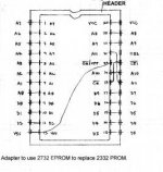
A little question: I did this adapter but it's refusing to work with 2716 (it worked with petester.bin on 2732).
Adapter to use 2732 eprom to replace 2332  prom.jpg

is there a different adapter for 2716 in 2316 socket?

Thank you guys, I'm going to sleep quite happy!

cheers,
Giovi
 
Last edited:
Excellent! Getting closer all the time...

Sorry, I actually had the petester.bin image (as pettester.txt) but sent you the wrong ones; thanks, Dave!

No adapter needed for a 2716, just plug it in; I think all the ROM sockets will take a 4kB (2532) or a 2kB (2716), although of course normally they're all 4kB except the 2kB E ROM.

Checking that there's continuity of every data and address line across all the ROM chips and the I/O chips and tracing the chip selects back to the decoder should have identified any bad sockets.

Maybe trace the I/O chip interrupt lines?
 
Last edited:
Excellent! Getting closer all the time...
Sorry, I actually had the petester.bin image (as pettester.txt) but sent you the wrong ones; thanks, Dave!

Have you a petester.bin for 8032 too? My spare 8032 board sometimes is doing strange things, so when the 3032 will be ok, I wish to do a try...

No adapter needed for a 2716, just plug it in; I think all the ROM sockets will take a 4kB (2532) or a 2kB (2716), although of course normally they're all 4kB except the 2kB E ROM.

Fine, I didn't know, thank you!

Checking that there's continuity of every data and address line across all the ROM chips and the I/O chips and tracing the chip selects back to the decoder should have identified any bad sockets.

Maybe trace the I/O chip interrupt lines?

hhhmm, not sure about what you mean; I checked that the 6622 pin #21 is joined with 6520s pin #37 and 6502 pin #4, as shown in schematics. Is it what you suggested to do?

Since I socketed all chips, I could have introduced an error; is there any chip that could be -more probably than other- the faulty one?
 
Have you a petester.bin for 8032 too? My spare 8032 board sometimes is doing strange things, so when the 3032 will be ok, I wish to do a try...
I don't know if anyone else worked on a CRTC version, but Dave said that he is working on one; apparently the existing one has a problem. What would be a useful addition to both versions is a quick-and-dirty ROM checksum routine...
hhhmm, not sure about what you mean; I checked that the 6622 pin #21 is joined with 6520s pin #37 and 6502 pin #4, as shown in schematics. Is it what you suggested to do?
Yes, check that 6502 pin 4 is connected to all the IRQ pins on the I/O chips (6520 pins 37 & 38, 6522 pin 21).

Also check that each of the eight 6502 data lines is making good connection to the corresponding pins on each of the five ROM chips and the three I/O chips, and that the 12 address lines are connecting from the buffers B3 and C3 to the corresponding pins on each of the ROM chips.

Just checking: this is a 'virgin' board, i.e. no visible modifications or signs of previous repairs?
 
Last edited:
I don't know if anyone else worked on a CRTC version, but Dave said that he is working on one; apparently the existing one has a problem. What would be a useful addition to both versions is a quick-and-dirty ROM checksum routine...

ok.

Yes, check that 6502 pin 4 is connected to all the IRQ pins on the I/O chips (6520 pins 37 & 38, 6522 pin 21).

Already did, it's ok.

Also check that each of the eight 6502 data lines is making good connection to the corresponding pins on each of the five ROM chips and the three I/O chips, and that the 12 address lines are connecting from the buffers B3 and C3 to the corresponding pins on each of the ROM chips.

I did all this checks, it seems all fine.
I also swapped the B3 and C3 (74LS244) with two tested ones. No changes.
After the last test I removed both 6520 and tested again, no changes.
* I PLANNED TO LEAVE THE BOARD WITHOUT 6520 UNTIL THE END (it should boot without them, shouldn't it?); please tell me if it could generate problems and/or it's better to leave them on board.


Just checking: this is a 'virgin' board, i.e. no visible modifications or signs of previous repairs?
Yes, the only hurricane that passed on it in the past was the "hurricane Giovi" (me) ;-)


Now, the bad news: I didn't find a logic probe here in the city. So I have two chances:
1) buy one on eBay and wait about 2 months to receive it (well, since it costs 5 euros, I'm going to buy it just to have it in my tools box...)
2) try to make a logic probe with spare parts I have here at home.

Mike, in my previous post I passed you a schematics about a simple one. You told me something like "not a good one, but maybe it will work"; please can you tell me if I can make this way and still have some kind of result, or I have to wait for 2 months?
Or, have you some kind of schematics involving part I could have: npn transistors like bc547 or 2n3904; npn/pnp power transistors like tip14x, tip12x, etc.; 74 series ICs used in 3032 (I have some spare ICs of every type used in the 3032) ?
 
To tell the truth I'm not sure whether you can remove both 6520s; C6 almost certainly yes, and I *think* you can also remove C7 although of course you won't be able to 'do' anything. Does anyone have a 2001 or 30xx/40xx to confirm?

To tell the truth I'm not sure whether a logic probe will help much, but there are quite a few circuits, descriptions and even tutorials out there on the web for you to peruse, depending on what parts you have and how much time you want to spend on it... ;-) The simpler ones merely indicate high or low voltage levels although the relative brightness can be an important clue; some will also indicate no signal at all, or the no-man's zone between ~1.5 - 3.5V. The fancier ones will also have a pulse 'catcher' that will turn on and keep on an LED when it sees a brief pulse that you'd normally miss.

Whatever it does, it should isolate the probe so that putting it on a point in the system under test does not affect the signal being probed; what I didn't like about the circuit you posted was that only one of the LEDs was driven by the transistor while the other one and its ballast resistor were directly across the input.

What we really need is a logic analyzer, but presumably you don't have one; I've been thinking about how and where we go from here, but I'll have to think about it some more ;-)

Jeff had some ideas about finding where it's looping (if it indeed is) from the address lines; maybe he'll chime in.
 
...well, I've taken the info about removing both 6520 from here: http://www.dansretropod.com/commodore/pet-cbm-3032.aspx

But if it's interesting, I could do every future test twice, one with 6520s and another without.

On my side, having no knowledge, the only way I can do it alone is brute-force (change everything), that util now didn't pay a lot :-/

I haven't neither an oscilloscope nor a logic analyzer and there's no way to get one of them without to buy it (and they aren't cheap!).

So I was trying to look at the problem from another point of view, at least for a while, at least until you people will have some fancy ideas about how to do a diagnostic without the needed equipement :)

The facts:
- I changed all ICs with fresh and/or tested ones. So we would assume it's not an ICs problem.
- The power supply (transformer and big capacitor) is working fine (I checked with the 8032 board).
- We checked voltages and they seems ok (maybe I could check the voltage in some ICs pin or sensible point in the board..?).
- I extracted all ICs and replaced them with sockets, so we could also assume I could have done one or more mistake soldering.
- We know the CPU is working because the petester.bin kernal ROM worked fine.
- We also know that ram and video ram are ok.

So, rationalizing:

- What part of the circuit/what ICs we can assume are ok, basing on the petester.bin positive working test? CPU, kernal ROM, RAM, video ram, what more? 6522? 6520? buffers B3 and C3 (74ls244), 555...?

and

- What part of the circuit isn't working while board is running the petester.bin?

I think we could get focused on this part, and so:
- looking at this part, is there some ICs that would be more suspectable to cause the hang/looping? I could check them before (socket, ICs, traces).


Or, of course, brute-force would be: "check with the multimeter every pin of every socket I didn't checked yet"... ...about 400/500 pins to be checked. I already unsoldered and soldered them, so checking all isn't impossible; good way to become crazy, though... so please give me an idea or you' will be responsible for my future madness :D (just kidding)

...and of course it will exclude socket problems but will not detect interrupted traces (a good step ahead, though).

have a good night!

--Giovi
 
Last edited:
Yes, I'm pretty certain that it will start up at least partially with the PIAs removed and I'm pretty sure I've tried it, but I don't like to state things as fact unless I can confirm it; there are often too many misleading, irrelevant and downright wrong suggestions in threads like this and I don't want to waste anybody's time by adding another one. ;-)

The frustrating part is that almost every essential part of the computer appears to be working, so it is actually effectively a software (firmware,actually) problem; the CPU is running the program that starts at the RESET vector in the F ROM and moving along merrily until for some reason it hits a step in the program that isn't part of the plan, and the question is why.

The obvious problem is that in order to check the 'program' we need the computer to be working; as a matter of fact for a while I've had some ideas about using another computer, but if I actually do something and it actually works, it would not be in the near future.

If we can talk Dave (or Steve, hint, hint?) into adding a rudimentary ROM checksum routine to the PETtester that would go a long way to verify that the 'program' is effectively correct and some unexpected event has happened (or, more likely, an expected event has not happened). At least you can program an EPROM, which could be very useful.

Did you build the NOP generator? One thing that it would let you check even with only a meter is that the ROM chips are being selected, i.e. that the effective chip select voltages are more or less the same. You might check them anyway while the PETtester is running (pin 20 on each of the ROM chips and pin 23 on the three I/O chips); I *think* they should all be high, ~5V.

You could also replace the 6520 at C7 and see if the keyboard is being scanned by any chance.
 
Last edited:
Yes, I'm pretty certain that it will start up at least partially with the PIAs removed and I'm pretty sure I've tried it, but I don't like to state things as fact unless I can confirm it; there are often too many misleading, irrelevant and downright wrong suggestions in threads like this and I don't want to waste anybody's time by adding another one. ;-)

Ok; actually I put the 6520s back...

The frustrating part is that almost every essential part of the computer appears to be working, so it is actually effectively a software (firmware,actually) problem; the CPU is running the program that starts at the RESET vector in the F ROM and moving along merrily until for some reason it hits a step in the program that isn't part of the plan, and the question is why.

...and I must to confess I also did a try: I programmed the four eprom (kernal, edit and basic) and I checked one at a time. Of course nothing. We already knew it since we tested the checksum in the 8032, but just to be sure....

But let me understand well: do you think it would be in some way a firmware problem? The board should be fine but for some reason it hangs "loading the sysop" ?
Does it pinpoint the problem in the ROMs area?

The obvious problem is that in order to check the 'program' we need the computer to be working; as a matter of fact for a while I've had some ideas about using another computer, but if I actually do something and it actually works, it would not be in the near future.

If we can talk Dave (or Steve, hint, hint?) into adding a rudimentary ROM checksum routine to the PETtester that would go a long way to verify that the 'program' is effectively correct and some unexpected event has happened (or, more likely, an expected event has not happened). At least you can program an EPROM, which could be very useful.

yes, it would be fine!

Did you build the NOP generator? One thing that it would let you check even with only a meter is that the ROM chips are being selected, i.e. that the effective chip select voltages are more or less the same. You might check them anyway while the PETtester is running (pin 20 on each of the ROM chips and pin 23 on the three I/O chips); I *think* they should all be high, ~5V.

I checked pin 20 of every ROM and pin 23 of the three I/O ICs both with NOP gen and with petester: all of them showed 3.73v with NOP gen and 3.92v while petester was running.

You could also replace the 6520 at C7 and see if the keyboard is being scanned by any chance.

I did it, but apparently nothing changed. garbage -> black and no response hitting some keys.
 
I programmed the four eprom (kernal, edit and basic) and I checked one at a time. Of course nothing. We already knew it since we tested the checksum in the 8032, but just to be sure....

Giovi,
At this point I was pretty sure one of your ROMs was bad, but if you switched them already, it is hard to think what is broken.

Someone suggested checking the state of the address lines. This will give a clue as to what area of ROM your PET is stuck in a loop. On all the address lines starting with the most significant bit (A15 to A0) check to see what the voltage it is. There should be three voltage zones of interest. Those lines that are less than 0.8 V can be assumed to be a logic zero. Those above say 3.8 V can be assumed to be a logic one. those in-between can be assumed to be pulsing and giving an average voltage between a logic one and zero. A scope or logic probe could tell us exactly the state, but a voltmeter will do. I assume your ROMs are the BASIC 2 set? Using a disassembly of the code, we will know the the computer is trying to do.

Hang in there. Your PET is fighting us with a tough problem, but you will fix it in the end.
-Dave
 
Giovi,
At this point I was pretty sure one of your ROMs was bad, but if you switched them already, it is hard to think what is broken.

They only thing I didn't do yet is to swap the four ROMs together; I could do it, I only need to make two more 2732->2532 socket adapter (one I have and one is 2716, that fits directly).
If you think it's interesting, just tell "do!" and I will check it :)
But I'm thinking to start changing those ROM sockets with fresh ones; illogically, maybe, but I can't stop to think one of them could be faulty/stained...


Someone suggested checking the state of the address lines. This will give a clue as to what area of ROM your PET is stuck in a loop. On all the address lines starting with the most significant bit (A15 to A0) check to see what the voltage it is.

ehm, a little doubt. Looking at ROM schematics (320349-4.gif) I only see A0-A11; while I can see AB0 to AB15 on the CPU schematics.
So should I check the voltages on CPU pins AB0-AB15, on ROMs pins A0-A11, or all of them?
Sorry for the dummy question, but I'm a dummy, indeed :)

There should be three voltage zones of interest. Those lines that are less than 0.8 V can be assumed to be a logic zero. Those above say 3.8 V can be assumed to be a logic one. those in-between can be assumed to be pulsing and giving an average voltage between a logic one and zero. A scope or logic probe could tell us exactly the state, but a voltmeter will do.

ok please just let me know what pins to check and in which configuration (petester running or normal black screen?) and I will report you the voltages.

I assume your ROMs are the BASIC 2 set? Using a disassembly of the code, we will know the the computer is trying to do.

Yes, basic 2: 901465-01/02/03 and 901447-24 << is it the right one? It should be, but just to know...

Hang in there. Your PET is fighting us with a tough problem, but you will fix it in the end.
-Dave

ok, thank you! I told you it's evil, maybe an exorcism would help... ;-)
 
Look at all 16 address lines. Use all the normal ROMs (not pet tester) installed to see where it is looping. Yes you are using correct ROM information.
-Dave
 
I've got something here called 2kromshow.txt (looks like a binary), but it's not convenient right now to check it out; anybody recognize it? Could this be what we're looking for?
 
Well, I have some news for you!

I changed sockets for 1465-01/02/03 (then I ran out of sockets before to replace the 901447-24 socket, I will dig in my spare parts box to see if I can found one...).

here some comics stripes to better explain ;-)

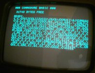
this is what sometimes I get after some on/off or after tapping the reset button few times!
2013-06-19-681_resize.jpg
The keyboard connector wasn't in; it started write some chars on the screen (poltergeists? gremlins?).. I attached the keyboard but it doesn't work;

Sometimes tapping the reset button I simply get one or more random chars on the screen. Sometimes it goes to black screen, sometimes it stops on the garbage.

this is the garbage:
2013-06-19-690_resize.jpg

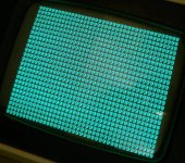
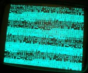
and these are the two petester screens endlessly looping.
2013-06-19-683_resize.jpg
2013-06-19-684_resize.jpg

(...continue on the next post....)
 
I discovered that if you leave the board to warm a bit (i.e. leaving the petester running) it stucks; at least, the petester stuck after a certain amount of time, don't know how much yet.
If you try to switch off and on again the only thing you get is the garbage or (in case you're running the petester) you get a random behaviour (garbage, petester running with screen refresh error, etc.). You have to wait some minutes, then he will get alive again.

I also changed the 6502 thinking it would be faulty and I got this screen:
View attachment 13970
(here you can see the memory count is wrong)

(I then tested both 6502, the one presumed faulty and this new one on the 8032 simply booting and running a 10 print"something";:goto 10).

It seems something get hot (even if I couldn't find an hot IC) and need a time to get cold again.

One more:
I've run the petester and it stuck in the middle showing some strips with chars mixed with some strips of "g". So I removed the other rom (except of course the char rom) and it started, but it's showing some "f" among "g" (not "b").

So I was happy something happend but I'm quite feared by this random behaviour, because of course random behaviours are the worst to diagnose... ...unless it's showing a detectable scheme that drive us to a certain IC or other defined problem...


------------ EDIT ---------------
...actually I'm stucked again in the garbage. Quite disappointing. Even the petester ROM stopped to work. ppppffffffffff...........
It seems something changed when I've changed the sockets. What I can say I did my best to make all correct, and I checked all pins of every socket against shortcut in every way I could imagine: i.e. pin 2 and 3, 3 and 4, but also mirrored pins like 2 and 20-19, etc.
Then I checked all pins were connected in the right way with same pins of other ROM chips...

The edit ROM socket was changed too.

Tomorrow I will check again every solder I did today.
 
Last edited:
...I've checked what I've done yesterday about the sockets, and it seems to be all fine.

I checked the ROMs pin 20; the kernal has some strange behaviour, sometimes is low (1.8 or less), sometimes is high (between 3.76 and 4.1). Sometimes is low at boot and then goes high after about 1", sometimes is high at boot and then goes low, sometimes has a value at boot (high or low) that doesn't change.
On the other three ROMs seems to be always high (4 v).

Pins 23 on the three I/O seems to be always high (about 4v).

I checked lines AB0-AB15 on 6502 (pins 9..20 and 22..25) and here the result is quite random; one time I got all at 3.76 V, another time I got (starting from pin 9): 1.21v, 2.44v, 1.21v, 3.75v, 0.2v, 0.2v and the other pins all 3.75v; etc.

I checked the DM74154 IC but it seems to work in the 8032.

Any idea? Later I will check one more time the sockets I changed yesterday, but I'm 99.9% sure it's all ok.

It seems that after some steps foreward yesterday (*** commodore basic *** screen) we've dropped back from the beginning: I can't exit from the garbage screen problem and I don't know what to do...

It **seems** (still not sure) the eprom -02 is running hot. Will check it and report later.

I also had (or still have?) a power connector problem: it run hot due to a poor contact. I cleaned it and should be ok, but I will check it too.

Any idea???? I'm quite disappointed and sad about that... :-(
 
Do not be discouraged as we have a lot of clues here.

...I've checked what I've done yesterday about the sockets, and it seems to be all fine.

I checked the ROMs pin 20; the kernal has some strange behaviour, sometimes is low (1.8 or less), sometimes is high (between 3.76 and 4.1). Sometimes is low at boot and then goes high after about 1", sometimes is high at boot and then goes low, sometimes has a value at boot (high or low) that doesn't change.
On the other three ROMs seems to be always high (4 v).
the F ROM should pulse low more than the rest in the beginning, but there may be a connectivity problem with some intermittents.

Pins 23 on the three I/O seems to be always high (about 4v).
address A8 always high? look for open on this circuit.

I checked lines AB0-AB15 on 6502 (pins 9..20 and 22..25) and here the result is quite random; one time I got all at 3.76 V, another time I got (starting from pin 9): 1.21v, 2.44v, 1.21v, 3.75v, 0.2v, 0.2v and the other pins all 3.75v; etc.
intermittents again


It **seems** (still not sure) the eprom -02 is running hot. Will check it and report later.
problem in D ROM area?
 
...ok, I solved this latest problem. A little piece of solder felt under one option ROM socket and was shortening intermittent pins 10 and 15. Quite hard to find, I had to remove all option ROM sockets (actually I left the board without these sockets).
I don't know if it was already there or, most probable, it happened when I changed the ROM sockets.

Now petester is running fine and endlessly, and normal ROM kernal has restored its original behaviour: garbage then black.

So I tested the 16 address lines (6502 pins 9 to 20 and 22 to 25):


6502 pins-:---9-----10-----11----12------13-----14-----15-----16-----17-----18-----19-----20-----22-----23-----24-----25
voltage---: 1.68 - 1.72 - 1.64 - 2.21 - 1.49 - 3.34 - 3.70 - 3.45 - 0.05 - 3.49 - 3.50 - 0.41 - 0.04 - 3.95 - 3.95 - 3.96
ref.schem.: AB0----AB1----AB2----AB3----AB4----AB5----AB6----AB7----AB8----AB9----AB10---AB11---AB12---AB13---AB14---AB15


Pin #23 of I/O IC (6522 and 6520s) are all 0.10v

ROMs pin #20: all 4.05, except for the edit rom (901447-24) that is 0.10

I still trying to understand what makes it to make a step ahead, yesterday, and display the text *** COMMODORE BASIC *** and the ram free....

Any idea?
 
Last edited:
Giovi,
Your PET seems stuck in the E6XX area of ROM (Editor) for some reason. I will look into the code for clues.

I thought at first your PIAs were stuck on also due to the signal I/O being low, but it is the same signal as Select E, so as long as the signal X8XX is low, the I/O is not enabled.
 
Back
Top