• Please review our updated Terms and Rules here

A pair of Pets - Preparing to test after perhaps 40 years unused

I see you have just posted the answer to my question...

So, is there actually a ROM fitted to UD10 (and UD11 come to that) on your board?

The character ROM is not connected to the data bus in any case. The character generator should be permanently enabled anyhow.

Dave
 
Yes, there should be a ROM fitted to UD10. I suspect this ROM to be defective (in the D6 department), or the IC socket and ROM pin for D6 are not making good contact.

However, this should not stop my PETTESTER from running correctly.

Dave
 
Can you check ALL of the data lines when UD6 (Kernal ROM) is selected. D6 looks a bit dubious there also - and I need this to work (or a handful of instructions at least) to enter my PETTESTER...

Dave
 
Like this? I've only got 8 inputs on my analyser so I've got UD6 CS and D0-6 below.

The two pictures are the same thing just different zoom.

Continuity is good on D6 along all ROM sockets (testing on the IC pins from top)

I've still got the NOP installed too.

8032-UD6-CS and D0-6.png


8032-UD6-CS and D0-6 Zoomed Out.png
 
It is really difficult to see, but there are somewhat less data bit transitions in the Kernal ROM than I would expect. Or is it my imagination I wonder?

Dave
 
I don't think this is getting us very far is it...

You can use the NOP generator and an oscilloscope to look for data bus contention. Using a logic analyser just makes contention look OK!

I would remove the NOP generator and go with the usual PET ROMs and my PETTESTER. Use your logic analyser to look at the /CS pins of the Kernal and EDIT (PETTESTER) ROM sockets and the /CS pin of the CRTC.

If you can force a reset with the power on, I would be interested to see what happens immediately after the reset (i.e. use the /RESET as the LA trigger).

Dave
 
I had the same thought (about less data when kernel active), but didn’t know what was normal.

I’m in bed now (our timezones are very inconvenient!) but would the same captures without the NOP or even PETTESTER help?

I wonder if I can use two of the cheap 8 channel USB analysers at the same time in Pulseview or Logic - I’ve only got 1 but they are very very cheap and easy to get if that meant 16 channels.

Edit: I’ll do what you suggest in the last post above tomorrow … scope without NOP.
 
Actually...how DO I look for bus contention with the NOP & scope?

At the moment I'm seeing the expected random mess...although with the occasional glitch in it...but perhaps data bus's always look like that?

(my last line in previous post should have read "Scope WITH NOP"....or Analyser without NOP)
 
Last edited:
Basically, connect the oscilloscope probe to (say) D0 and look at the waveform at different timebase settings. A bus 'clash' will be neither logic '0' or logic '1'. I am afraid this is 'art' and not 'science', so it is a bit like fishing - wait and see what you can see...

Dave
 
My wife refers to my mancave activities as "Arts & Crafts" (never actually asked why) so perhaps I can channel that. What about these little bits? (this is D0)
IMG_0115.jpg
Here's the Kernal/EDIT/CRTC CS lines after a reset triggered via J4 Pin 22 & a push button. I presume the little spikes are just bounce.

CS-reset.png
 
Last edited:
If the above is a smoking gun, I found which line on the decoder lines up with that glitch: UE12 PIN 9 (SEL 8)

(in image below, CH2 in Purple is D0 and CH1 in Yellow is on UE12). SEL 9 starts just after the glitch so pretty sure it's SEL 8 that would apply.

IMG_0117.jpg
 
Last edited:
D0 looks OK.

/SEL8 is the screen and /SEL9 is probably a ROM that is not fitted to your board. I would guess it is /SEL9 (as none of the data bus lines will be driven by a ROM) - but it could also be the end of /SEL8 leading into /SEL9 (if the screen RAM is fully decoded - i.e. not all of $8xxx actually drives the data bus). The screen occupies RAM from $8000 to $87FF - so $8800 to $8FFF can be 'empty'.

Did you take the logic trace with (or without) the NOP generator.

If you took it without the NOP generator being fitted, what we are seeing is not correct...

Dave
 
Did you take the logic trace with (or without) the NOP generator.
With NOP


Before I read your reply, I was following SEL8 to see what it activated & test it's data lines.

EDIT: following paragraph is rubbish - I was counting as if it was a 18-pin IC, not 20.

***I'm not sure if they are relevant (I didn't fully check the logic that led me here) but measured UB4 & UB5 and found that both have pins 17&18 (BD0 and BD4) permanently HIGH. Is that expected? They seem to be directly connected to the same data lines on J4 where I've been taking measurements & I haven't worked out why the signal there is different.***
 
Last edited:
>>> With NOP

Ah, that would explain the trace... I suggested:

I would remove the NOP generator and go with the usual PET ROMs and my PETTESTER. Use your logic analyser to look at the /CS pins of the Kernal and EDIT (PETTESTER) ROM sockets and the /CS pin of the CRTC.

Dave
 
I would remove the NOP generator and go with the usual PET ROMs and my PETTESTER. Use your logic analyser to look at the /CS pins of the Kernal and EDIT (PETTESTER) ROM sockets and the /CS pin of the CRTC.
That's the image a few up in post #190 (No NOP, CS traces and performed reset with J4). We see the CS on Kernal only, nowhere else.
 
In that case, your Kernal ROM (for whatever reason) is not behaving correctly.

It should fetch the restart vector from the Kernal ROM, execute a handful of instructions in the Kernal ROM, and then enter the EDIT ROM (PETTESTER) and stay there forever. You should observe 16 (or so) pulses on the CRTC chip select.

Dave
 
Continuity from the Kernal to CPU at least is all 100% on A and BD lines (tested via the buffers) so it doesn’t seem to be as simple as a trace or joint.

My 2332-2732 PCBs have shipped from PCBWAY so I think I’ll wait for those to arrive and see what’s happens with a known good ROM - maybe my breadboard adapter just wasn’t right.

It’s still at the back of my mind that I thought something fizzled out when the whole thing stopped working “mid probing”. Could some passive failure cause this?

Maybe I better put the 6502 in one of my VICs and check that it’s still working too.
 
One thing that can sabotage quick fault finding is that there can be two or more problems affecting the computer at the same time. Which can sometimes confound the testing and slow things down.

In my PET repair box I made a NOP generator with an on board address range decoder. This way I could use that to sync the scope over a specific address range on one channel, and use the other scope channel to inspect events that were occurring over that range only. I had noticed though using the NOP, on the scope at times there did appear to be some data line conflicts at times, not seen with the computer in normal use.

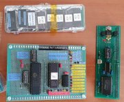
I also made a circuit where the DRAM is dynamically deactivated below the 1k or 2k boundary and replaced with SRAM switched in (the board on the right in the photo). This way I would recover the operating system if DRAM was damaged and then I could use simple test programs to analyze the DRAM and home in on the defective chips that in many cases are soldered in.

But of all the test circuits I made and Daver2's wonderful PET tester too, the thing I found helpful was to do two things to help speed up a repair.

1) One was to make a full set of good ROM's.

2) Then check all of the ROM's socket pins for tension, using a defunct IC pin soldered to a wire handle, just to make sure all of the ROM IC socket claws were ok.

Then I would simply fit all of the known good ROMs together. This eliminated all of the ROMs & sockets as a cause of the fault, then I could simply get on and find out which other IC's were defective.

If a fault cleared or altered after doing this I would simply then substitute the original ROMs back in, one by one, to find out which ROM/or ROMs were defective. On one PET board I fixed, 3 ROMs were defective !

I'm not sure how they got like that. I assume they were probably plugged in, in reverse, by a previous owner would be my best guess.
 

Attachments

  • PETDIAGNOSTIC.jpg
    PETDIAGNOSTIC.jpg
    248.9 KB · Views: 6
I just need to convince you to take a drive south with your gear Hugo ….it would save Daver2 a lot of effort leading me through this!

When my adapter PCBs arrive I’ll be able to to make up replacement ROMs to my hearts content - I’ll not rip them all up immediately but if it comes to it, I can.
 
I finally got my 2332 -> 2732 PCBs.

Using a 2732 in UD6 (with Kernal on it) is NEARLY the same as the real Kernal IC. I say "nearly" because the chip select sits at 68 khz on the EPROM but 76.9 with the real one. I swapped back and forwards a few times and it's consistent for whatever reason but otherwise everything failing just as it did before.

I also checked the PETTESTER again just in case it's code was bad, it verified OK.

EDIT: After a bit more testing, after power up, sometimes the active CS moves to UD7 / EDIT instead. I.e. it will flatline HIGH on UD6 and be oscillating on UD7 instead. If I wait long enough it will eventually flatline HIGH again.
 
Last edited:
Back
Top